System and method to identify regions of airspace having ice crystals using an onboard weather radar system

a technology of airspace and weather radar, which is applied in the direction of reradiation, instruments, and clear air turbulence detection/forecasting, etc., can solve the problems of power loss, power loss of jet engines or even engine damage, and aircraft passing through airspace regions with high concentrations of ice crystals

Active Publication Date: 2015-11-17
HONEYWELL INT INC
View PDF15 Cites 13 Cited by
  • Summary
  • Abstract
  • Description
  • Claims
  • Application Information

AI Technical Summary

Problems solved by technology

High altitude ice crystals that are not visible to the crew of an aircraft, especially at night, may present a hazard to the aircraft passing through an airspace region having high concentrations of the ice crystals.
Such ice crystals, which may be encountered while flying through clouds, may cause power loss in a jet engine or even engine damage.
Power loss may include engine instability, power surge, power rollback, stalling, and / or flameout.
Further, high altitude winds may blow the ice crystals away from the convective cloud formations.
Thus, the crew may not be aware that their aircraft is travelling through an airspace region having a high concentration of ice crystals, particularly if there is no turbulence and / or if the airspace region is not near any convective cloud formations.
Further, conventional aircraft weather radar systems are typically not configured to detect ice crystals since the reflectivity levels of return echoes from the ice crystals and / or the associated cloud cover, which may be in the range of 0-20 decibels (dBZ), is below the radar return sensitivity threshold levels, typically set at or about 20 dBZ.

Method used


Image

  • System and method to identify regions of airspace having ice crystals using an onboard weather radar system
  • System and method to identify regions of airspace having ice crystals using an onboard weather radar system
  • System and method to identify regions of airspace having ice crystals using an onboard weather radar system

Examples


Embodiment Construction

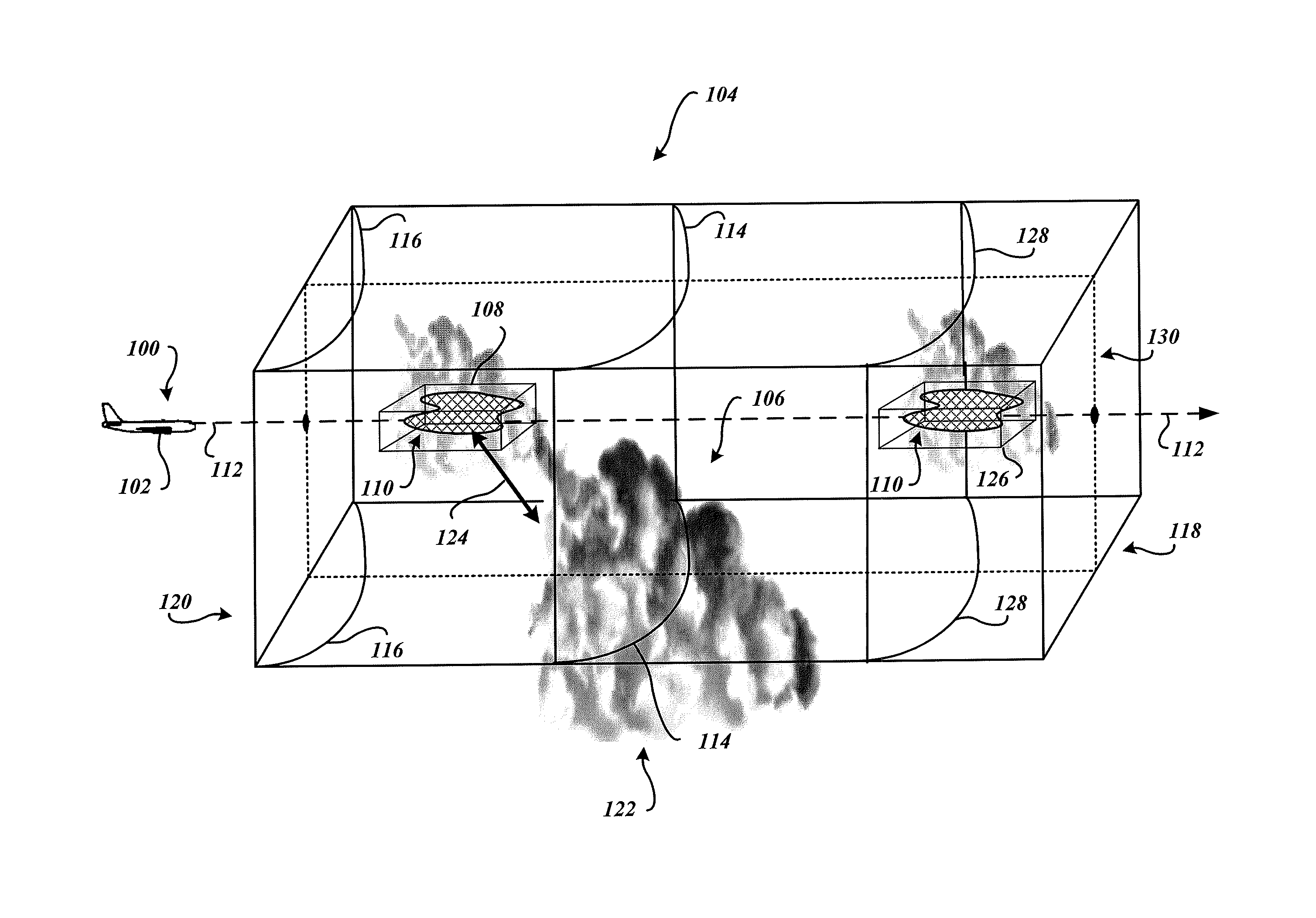
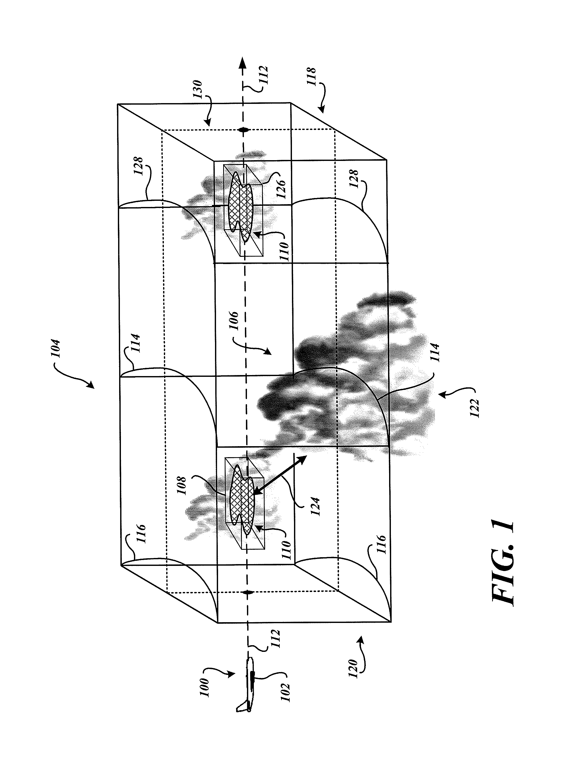
[0014]FIG. 1 is a perspective view of a portion of a planned flight path of an aircraft 102 traveling through a region of airspace 104 having convective cloud weather 106 and traveling through a region of airspace 108 with type I crystals 110. The aircraft includes an onboard weather radar system with an embodiment of a type I ice crystal display system 100. For clarity, ice crystals are defined as either type I ice crystals or type II ice crystals herein.

[0015]Type I ice crystals are defined herein as ice crystals typically found at altitudes between 9,000 and 40,000 feet, and / or when the ambient temperature is between −5° C. to −55° C. These high altitude type I ice crystals are associated with the convective cloud weather 106. Type I ice crystals are often not visible to the crew of the aircraft 102, and may be encountered while flying through relatively light cloud cover. Type I ice crystals are not associated with liquid water droplets. That is, liquid water droplets are not pr...


PUM


Abstract

Systems and methods of detecting type I ice crystals using an aircraft's onboard weather radar system are disclosed. An exemplary embodiment identifies radar returns having a return level signal strength less than a radar return sensitivity threshold level, determines if at least one of a weather condition and a flight condition concurrently exists with the identified radar returns having the return level signal strength less than the radar return sensitivity threshold level, and identifies a region of airspace potentially having type I ice crystals when the at least one of the weather condition and the flight condition concurrently exists with the identified radar returns having the return level signal strength less than the radar return sensitivity threshold level.

Description

PRIORITY CLAIM[0001]This application claims priority to Provisional Patent Application Ser. No. 61 / 608,562 filed on Mar. 8, 2012 and is incorporated herein by reference.BACKGROUND OF THE INVENTION[0002]High altitude ice crystals that are not visible to the crew of an aircraft, especially at night, may present a hazard to the aircraft passing through an airspace region having high concentrations of the ice crystals. Such ice crystals, which may be encountered while flying through clouds, may cause power loss in a jet engine or even engine damage. Power loss may include engine instability, power surge, power rollback, stalling, and / or flameout.[0003]These non-visible ice crystals may be found at altitudes between 9,000 and 40,000 feet, when the ambient temperature is between −5° C. to −55° C. High altitude ice crystals are typically associated with convective cloud formations, such as isolated cumulonimbus cloud formations, thunderstorms, or even tropical squall lines. Such convective...

Claims


Application Information

Patent Timeline
Patent Type & Authority Patents(United States)
IPC IPC(8): G01S13/00G01S13/95G01S7/06G01W1/00B64D15/20G01W1/08
CPCG01W1/00G01S7/062G01S13/953B64D15/20G01W1/08G01W2001/003G01W2203/00Y02A90/10
Inventor BUNCH, BRIAN P.CHRISTIANSON, PAUL
Owner HONEYWELL INT INC
Why Eureka
Try Eureka