
Taxi obstacle detecting radar

a radar and obstacle detection technology, applied in the field of weather radar and aircraft runaway incursions, can solve the problems of not allowing the aircraft to operate autonomously, targets without transponders are not detectable, last largely unsolved problems, etc., and achieve the effect of avoiding the lowest target miss rate and avoiding the problem

Active Publication Date: 2008-05-27
ROCKWELL COLLINS INC
View PDF10 Cites 46 Cited by
  • Summary
  • Abstract
  • Description
  • Claims
  • Application Information

AI Technical Summary

Benefits of technology

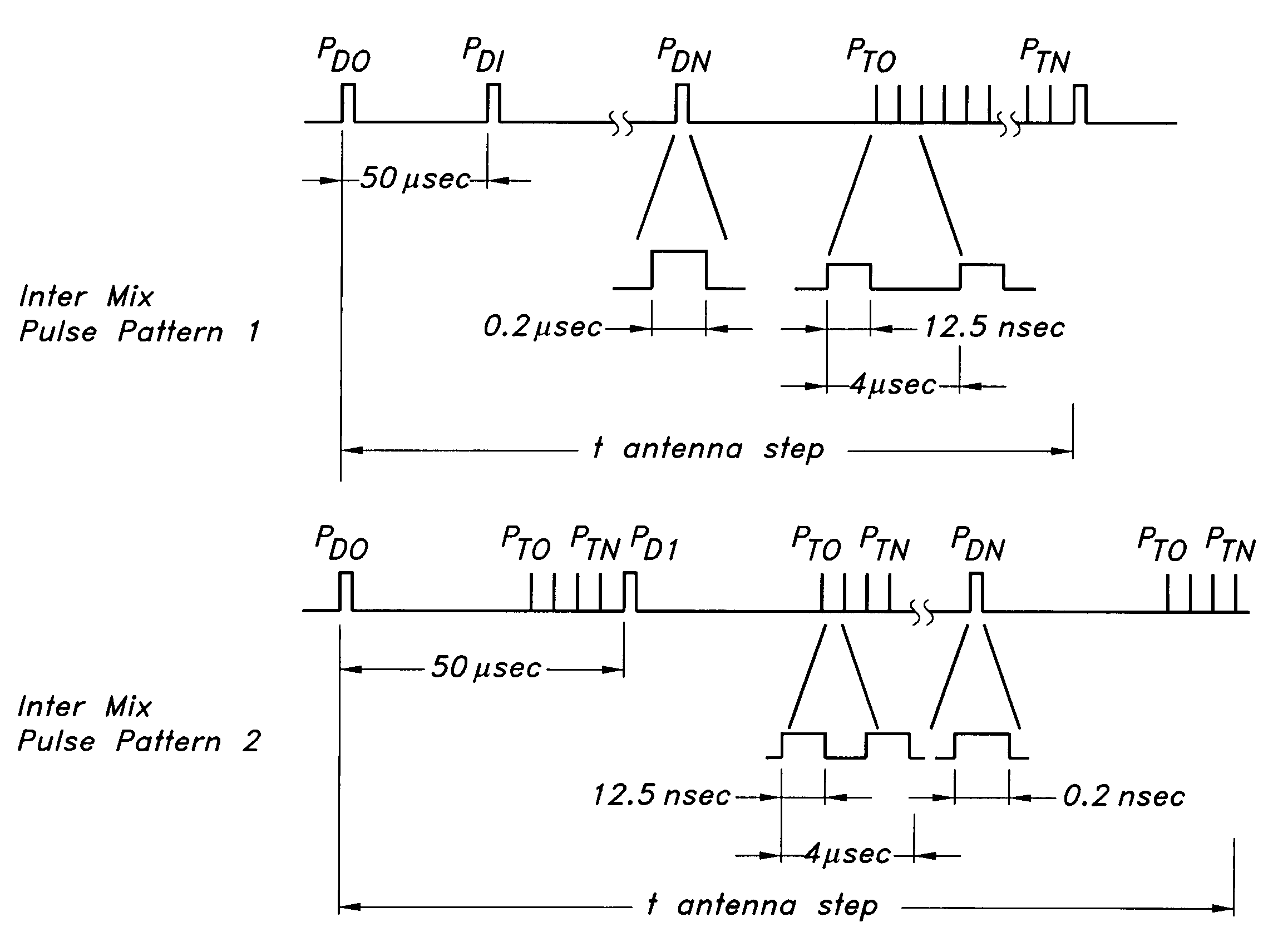
[0025]It is an advantage of the present invention to provide a weather radar with split detection ranges of short-pulse / short range and longer-range Doppler pulses to allow the radar to deal with the problem cheaply.
[0026]It is an advantage of the present invention to produce the lowest target miss rate possible in all environments.
[0027]It is a feature of the present invention to solve the ground movement problem when added to existing or pending taxi guidance systems.
[0028]It is a feature of the present invention to provide short and long-range modes without the need for expensive additions to new radar designs.

Problems solved by technology

Accidents during surface operations remain one of the last largely unsolved problems of the air transport system.
The real challenge is to make an aircraft safe in all environments.
Since this system is ground based, it does not allow the aircraft to operate autonomously.
Secondly, since this multilateration system tracks targets by L-band emissions, targets without a transponder are not detectable.
This solution does not require cooperation from a viewed target but does not work in some fog situations.
Millimeter wave systems have been demonstrated from several vendors but again they may be challenged with fog and cloud cover in the passive systems while the active systems are heavily attenuated in rain.
Both the IR and millimeter wave systems are costly and also carry a new maintenance burden as airline operators try to maintain the new higher frequency equipment and new IR window or dual-band millimeter wave capable radomes.
This system's weak point is in only annunciating runway / taxiway transitions, it does not directly detect threats.
Thus this system will not protect the aircraft from someone else who makes a mistake or obstacles that are not contained in the database.
This approach will violate the dark / quiet cockpit philosophy and may lead the pilot to discount an accident avoiding annunciation since the system is producing annunciations that are discounted all the time.
Assuming a guidance or position awareness system, such as these, is included in new aircraft, the problem becomes one of detection and annunciation of threats.
Unintended objects on the runways that were never expected to cooperate or aircraft with missing or broken equipment are examples of obstacles that would produce misses.
High detection rates for non-cooperative systems come at the cost of false alarms.
This may make certification somewhat of a challenge for any non-cooperative sensor system unless the environmental and target conditions are limited during certification as was done in certification standards for windshear detecting weather radar.
Both cooperative and non-cooperative systems face challenges.
So the problem that remains is that of obstacles and aircraft not being equipped to cooperate or not in the current database.
Both millimeter and laser radars do not work in moderate to high rain rate situations.
Ground movement threat assessment may be broken into two problems, short-range obstacles and longer range moving obstacles.
The short-range problem is one of providing the pilot with timely information to allow the aircraft to be braked to a stop.
The inclusion of non-moving targets brings a potentially higher false alarm opportunity unless a database is used to qualify which targets are in the taxi path of the aircraft.
The longer-range problem only addresses moving targets.

Method used


Image

  • Taxi obstacle detecting radar
  • Taxi obstacle detecting radar
  • Taxi obstacle detecting radar

Examples


Embodiment Construction

[0035]The present invention is for a weather radar system used for obstacle detection during taxi operations. A weather radar that is already on-board aircraft such as commercial airliners may be modified or a new weather radar developed to detect ground obstacles. The weather radar of the present invention uses a short-range (short transmitter pulse) detector and a longer-range Doppler-aided closing target detector. Weather radar may be used for obstacle detection during taxi operations since the weather function is generally either not being used or if used the update rate for weather information may be very slow.

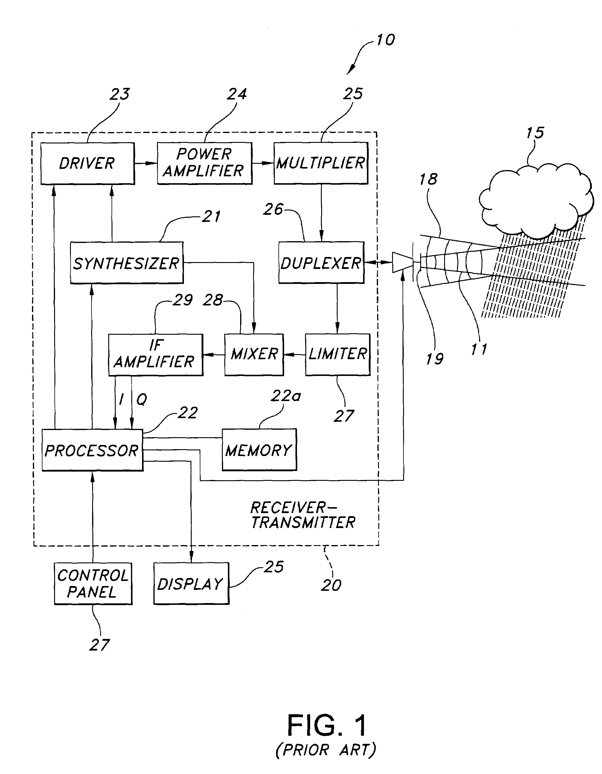
[0036]Weather radars are known in the art for detecting severe weather and for providing a flight crew in an aircraft a two dimensional map display showing range bearing and intensity of detected weather patterns. Flight hazards due to weather conditions are primarily the result of precipitation and turbulence. A block diagram of a representative weather radar 10 that may...


PUM


Abstract

A weather radar for detecting taxi obstacles has a transmitter for transmitting intermixed short-range pulses to detect short-range stationary objects and longer-range Doppler pulses to detect long-range moving targets. A receiver receives short-range return pulses from the short-range stationary objects and longer-range Doppler return pulses from the long-range moving targets. A processor is connected to the transmitter and receiver for generating the intermixed short-range pulses and longer-range Doppler pulses and for processing short-range return pulses and longer-range Doppler return pulses. A display displays detected short-range stationary objects and longer-range moving targets.

Description

CROSS REFERENCE TO RELATED APPLICATIONS[0001]The present application is related to co-pending application Ser. No. 10 / 631,316 filed on Jul. 31, 2003 entitled “Runway Obstacle Detection System and Method” by Daniel L. Woodell. The co-pending application is assigned to the assignee of the present invention.BACKGROUND OF THE INVENTION[0002]This invention relates to weather radar, aircraft runaway incursions, and specifically for a weather radar for the detection and alerting of the presence of obstacles during taxi operations.[0003]Accidents during surface operations remain one of the last largely unsolved problems of the air transport system. Both the US government and resources from a number of companies are moving to meet this challenge. Many have suggested solutions that require controlled environments, ground equipment, or equipment on all vehicles or structures that may be involved in an accident. Counting on these external requirements always being in place insures some situatio...

Claims


Application Information

Patent Timeline
IPC IPC(8): G01S13/00G08G1/16
CPCG01S13/87G01S13/931G01S13/953G08G5/045G08G5/065G01S2013/916G08G5/06Y02A90/10G01S13/934
Inventor WOODELL, DANIEL L.ROBERTSON, ROY E.
Owner ROCKWELL COLLINS INC
Learn More