Display device

a display device and display technology, applied in the field of display devices, can solve the problems of poor visibility in the oblique direction, low aperture ratio, and many development difficulties, and achieve the effect of improving light utilization efficiency and increasing brightness

Inactive Publication Date: 2005-11-22
FUJIFILM HLDG CORP +1
View PDF2 Cites 79 Cited by
  • Summary
  • Abstract
  • Description
  • Claims
  • Application Information

AI Technical Summary

Benefits of technology

[0028]In the display device, incident light can be converged by the microlenses to the light modulating regions of the light modulating elements. The light is not blocke

Problems solved by technology

A liquid crystal display device has further disadvantages that it shows a viewing angle dependence and is poor in visibility in an oblique direction, and that components such as a driving circuit formed on the display face do not transmit light and hence the aperture ratio is low.
However, the development involves many difficulties.
Furthermore, an organic EL display device has problems such as that the amount of light is remarkably reduced by deterioration of a material and an

Method used


Image

  • Display device
  • Display device
  • Display device

Examples


first embodiment

(First embodiment)

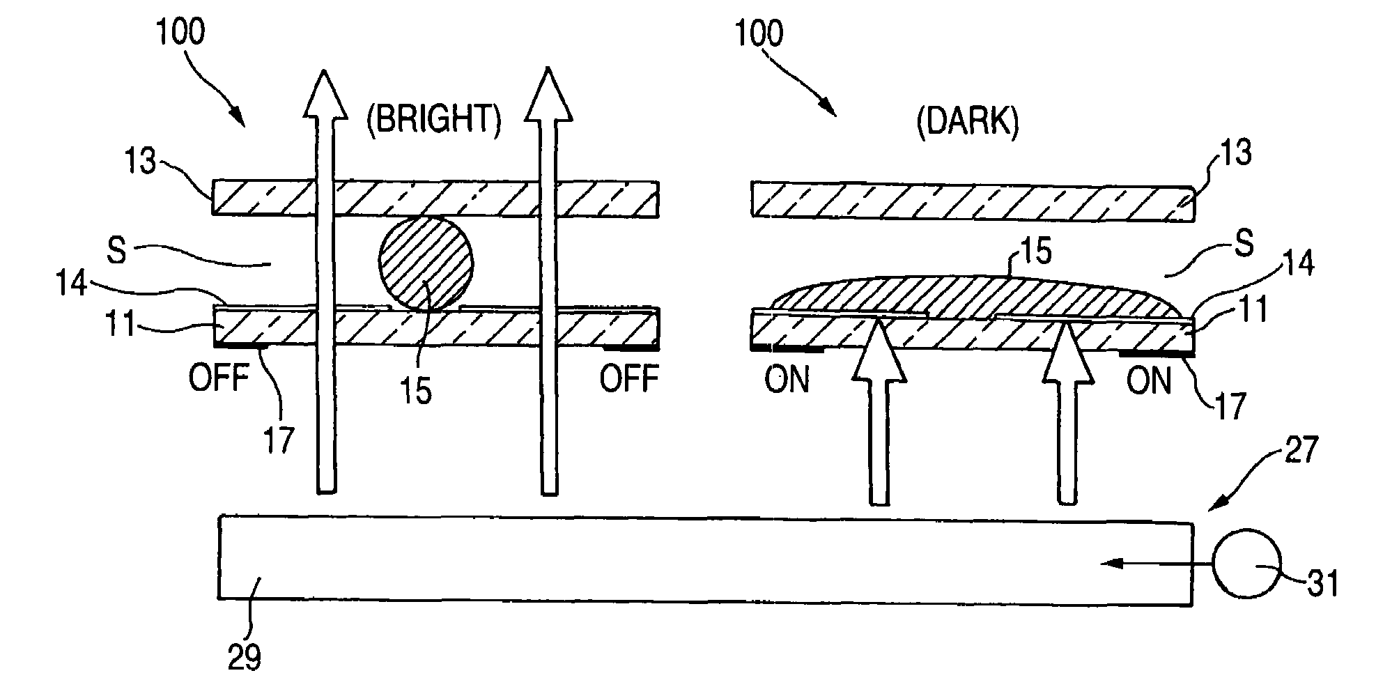
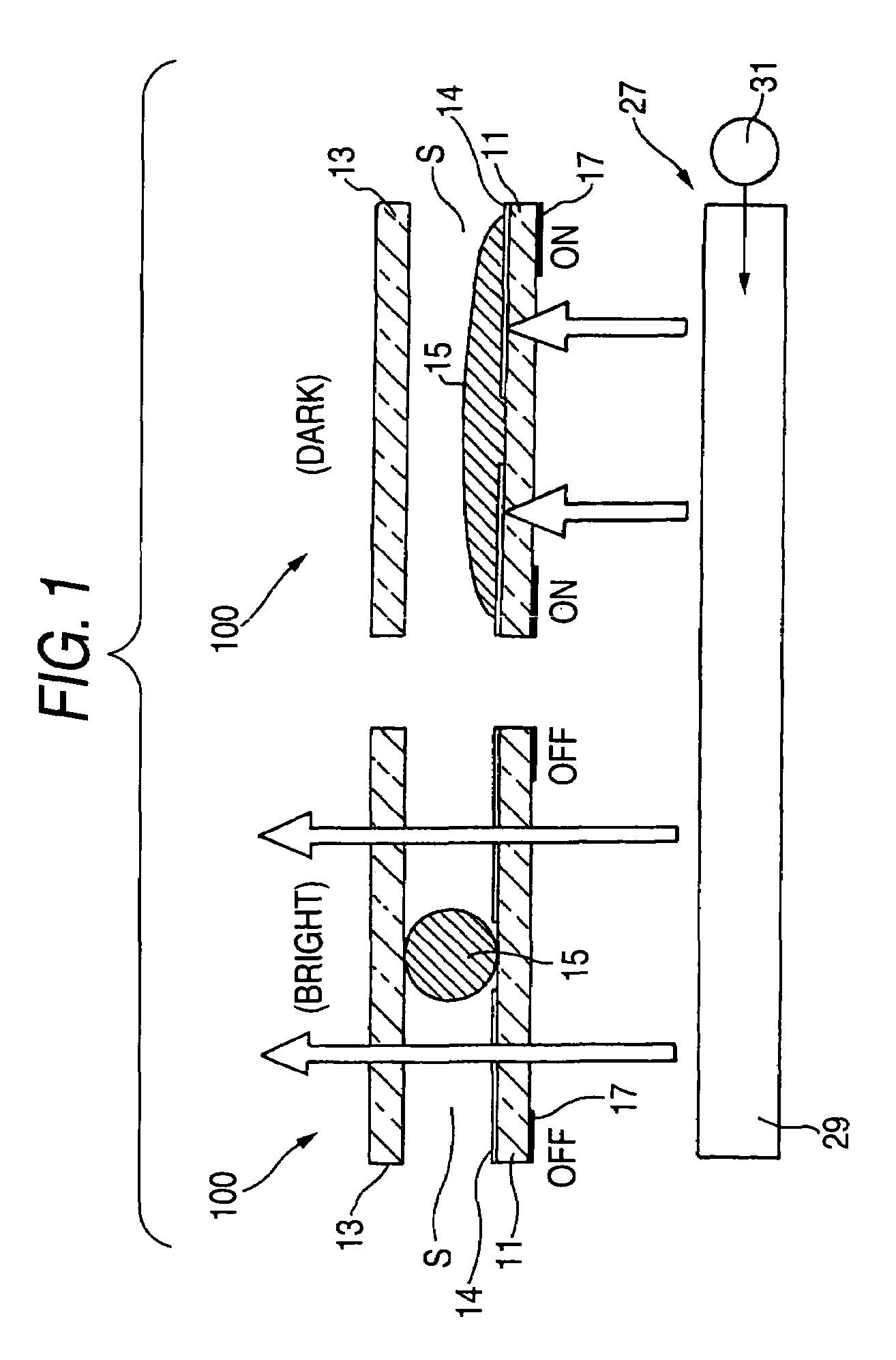
[0043]FIG. 1 is a section view of a light modulating element constituting the display device of the invention.

[0044]The light modulating element 100 has a pair of first and second transparent substrates 11 and 13 which are opposed to each other with being separated by a predetermined distance. A colored fluid 15 which is colored in, for example, black is enclosed in a sealed space S formed by a gap between the first and second substrates 11 and 13. In the first substrate 11 over which the colored fluid 15 is to wet and spread, a water / oil repellent film 14 is formed on the surface in which a middle area is excluded, and which is used for forming the sealed space S.

[0045]As the first and second substrates 11 and 13, it is requested to use a light-transmittable material. Preferably, plastic or glass is used. Although the water / oil repellent film 14 is formed on the surface of the first substrate 11, a water / oil repellent film may be formed on the surfaces of both the...

second embodiment

(Second Embodiment)

[0078]Next, a second embodiment of the display device of the invention will be described. In the following description, components having the same functions as those of the display device of the first embodiment are denoted by the identical reference numerals, and their description is omitted.

[0079]FIG. 5 is a section view of a light modulating element which performs light modulation with using a piezoelectric member as a driving source.

[0080]In the light modulating element 120 constituting the display device 210, a void 33 is formed in the first substrate 11. A face of the void 33 which is on the display side is formed as a diaphragm portion 11a which is elastically deformable.

[0081]As a driving section which deforms the colored fluid 15, a light-transmittable piezoelectric member 35 which has a thin film-like shape is disposed on the face of the diaphragm portion 11a which is on the display side. Although not shown, in the piezoelectric member 35, the aforementi...


PUM


Abstract

A display device comprises a plurality of light modulating elements being arranged in an array. In the display device, an image is displayed by driving the light modulating elements and each of the light modulating elements has a pair of substrates which are spaced apart from each other; a fluid which is enclosed in a sealed space formed by a gap between the substrates; and a driving section which deforms the fluid in the sealed space to control an area of the fluid in the sealed space, the area extending in a face of at least one of the substrates, thereby adjusting an amount of transmitted light or reflected light.

Description

BACKGROUND OF THE INVENTION[0001]1. Field of the Invention[0002]The present invention relates to a display device, and more particularly to a technique of conducting a displaying process with high brightness and excellent contrast.[0003]2. Description of the Related Art[0004]In the related art, as a display device which displays characters, an image, and other information, known are devices such as: a liquid crystal display device in which a liquid crystal display element and polarization plates are combinedly used, and orientations of liquid crystal molecules are controlled by applying a voltage to display an image; an organic EL display device in which an organic compound that becomes self-luminous in response to application of a voltage is used for displaying an image; and an electrophoretic display device in which a colored medium is placed between electrodes, and the colored medium is electrophoresed by application of a voltage to be moved toward one of the electrodes, thereby ...

Claims


Application Information

Patent Timeline
IPC IPC(8): G02B26/02
CPCG02B26/004
Inventor FUJII, TAKAMICHIHARADA, AKINORI
Owner FUJIFILM HLDG CORP
Why Eureka
Try Eureka