Supercharge Your Innovation With Domain-Expert AI Agents!

Electrical connector

a technology of electrical connectors and connectors, applied in the direction of coupling contact members, coupling base/cases, coupling device connections, etc., can solve the problems of increasing the insertion force of the fitting to the mating connector, the electrical connection between the terminals may become unstable, and the connector feels heavy, so as to achieve effective removal of foreign substances, improve the ability to remove foreign substances, and improve the effect of foreign substance removal

Inactive Publication Date: 2015-11-17
IRISO ELECTRONICS CO LTD
View PDF30 Cites 8 Cited by
  • Summary
  • Abstract
  • Description
  • Claims
  • Application Information

AI Technical Summary

Benefits of technology

[0006]The present invention has been made to solve the above problem, and it is an object of the present invention to provide an electrical connector having a terminal that can remove a foreign substance effectively, and that provides a good insertion feeling.

Problems solved by technology

If the foreign substance is caught between the contact of the terminal and the mating terminal, electrical connection between the terminals may become unstable.
However, if two terminal portions are provided, contact pressure of each terminal portion is applied to the mating terminal, and therefore insertion force when fitting to the mating connector increases.
Therefore, compared to the case where the number of terminal portions is one, the connector feels heavy for an operator fitting the connector, and operability deteriorates.

Method used


Image

  • Electrical connector
  • Electrical connector
  • Electrical connector

Examples


Embodiment Construction

[0025]The present invention will be described by way of embodiments in more detail.

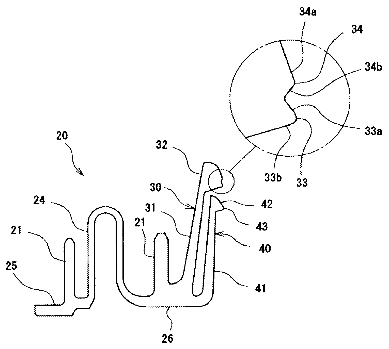
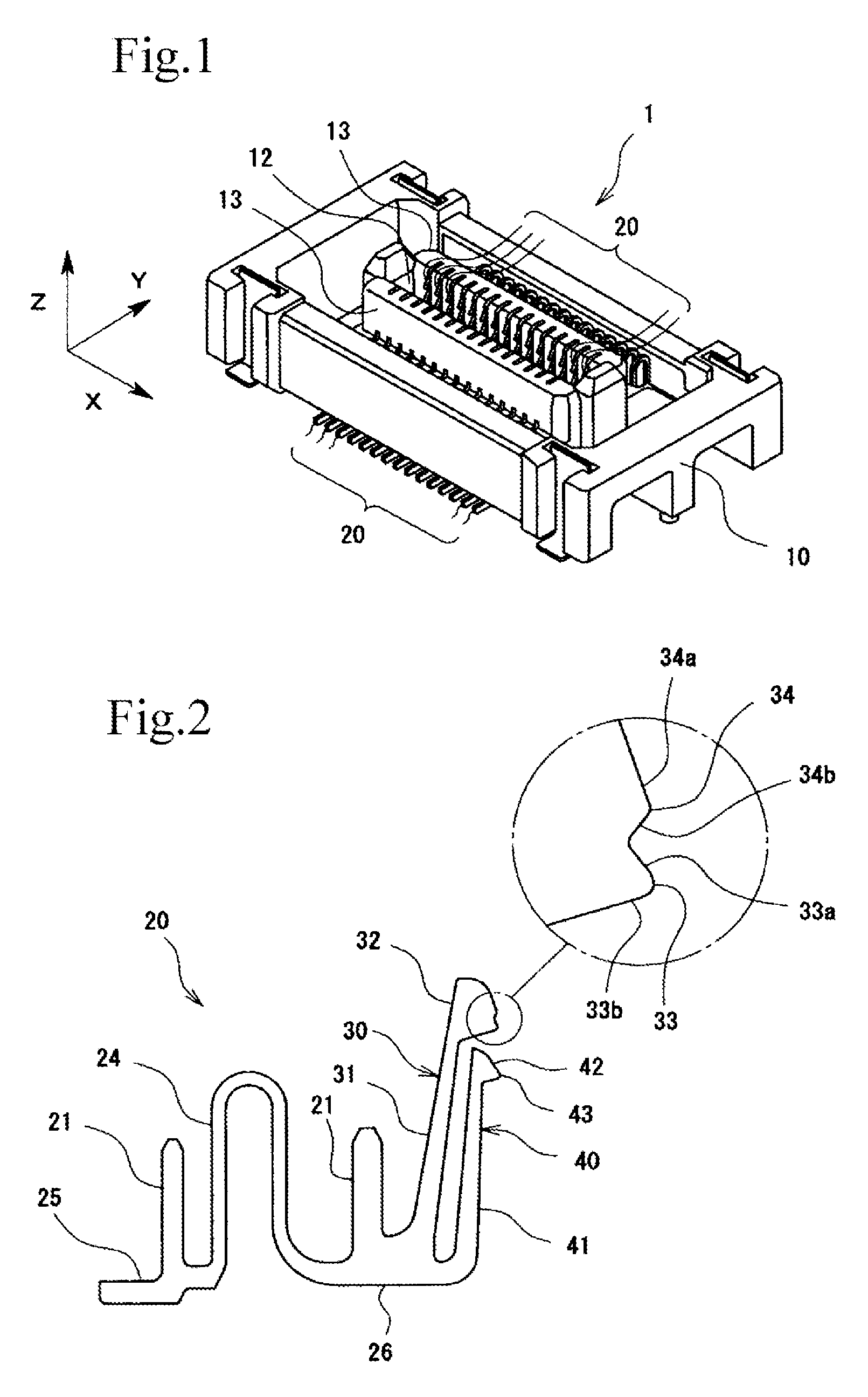
[0026]FIG. 1 is a perspective view of an electrical connector 1 in which terminals 20 are assembled to a housing 10. The electrical connector 1 is installed on a member to be connected (not shown) such as a printed board, and is fitted to a mating connector (not shown) installed on another printed board or the like. The terminals 20 of the electrical connector 1 come into contact with mating terminals of the mating connector, and the printed boards are thereby electrically connected to each other.

[0027]In the description of this specification and claims, for convenience sake, the X direction of FIG. 1 will be referred to as a width direction, the Y direction will be referred to as a front-rear direction, and the Z direction will be referred to as a vertical direction (insertion and removal direction). However, the installation direction or the use direction of the electrical connector 1 is not determi...


PUM


Abstract

An electrical connector includes a terminal that includes a front terminal portion, and a rear terminal portion the contact position of which is located further from the insertion opening of the connector than the contact position of the front terminal portion, and that is electrically connected with a mating terminal as an object to be connected. The front terminal portion has a front elastic arm, and a front contact portion formed at the distal end of the front elastic arm, and the front contact portion has a front contact that comes into contact with the mating terminal, and a dummy contact that is located closer to the insertion opening of the connector than the front contact, and that wipes a foreign substance adhering to the mating terminal.

Description

BACKGROUND OF THE INVENTION[0001]1. Field of the Invention[0002]The present invention relates to an electrical connector having a terminal having a contact that wipes a foreign substance and a contact that is electrically connected to a mating terminal.[0003]2. Description of the Related Art[0004]A foreign substance such as board debris or dust may adhere to the surface of a mating terminal to which a terminal is electrically connected. If the foreign substance is caught between the contact of the terminal and the mating terminal, electrical connection between the terminals may become unstable. As a countermeasure, there has been known a terminal including two terminal portions having contacts at the distal ends thereof, one of the contacts being formed for wiping a foreign substance, and the other being formed for electrical connection with a mating terminal. Such a terminal is described, for example, in Japanese Unexamined Patent Application Publication No. 2012-69243.[0005]Howeve...

Claims


Application Information

Patent Timeline
Patent Type & Authority Patents(United States)
IPC IPC(8): H01R13/11H01R12/71H01R12/73H01R13/52
CPCH01R12/716H01R12/73H01R13/52H01R13/26H01R12/91
Inventor TAKAKI, MASATO
Owner IRISO ELECTRONICS CO LTD
Features
  • R&D
  • Intellectual Property
  • Life Sciences
  • Materials
  • Tech Scout
  • Unparalleled Data Quality
  • Higher Quality Content
  • 60% Fewer Hallucinations
Learn More