Rotational driver

a technology of rotational action and driver, which is applied in the field of surgical suturing devices, can solve problems such as lack of disclosure, and achieve the effects of effective suturing, enhanced maneuvering and safety of suturing procedures

Active Publication Date: 2015-11-24
ERGOSURGICAL GRP CORP
View PDF5 Cites 387 Cited by
  • Summary
  • Abstract
  • Description
  • Claims
  • Application Information

AI Technical Summary

Benefits of technology

[0012]The disclosed invention provides an effective suturing device that enhances the maneuvering and safety of suturing procedures. The rotational driver comprises a interactive portion, wherein each interactive portion comprises a first extended member and a second extended member, a rotational system a linear motion system, wherein said first extended member comprises a first distal end, a first proximal end and a first main extended member body, wherein said first main member body in between said first distal end and said first proximal end, wherein said first distal end comprises a first contact distal end, wherein said second extended member comprises a second distal end, a second proximal end and a second main member body, wherein said second main member body is between said second distal end and said second proximal end, wherein said second distal end comprises a second contact distal end, wherein said rotational system comprises a rotational actuator mechanically coupled to at least an action transmitter mechanism, wherein said action transmitter mechanism is mechanically connected to said first extended member providing rotating action upon said first distal end; and wherein said first distal end and said second distal end contact each other in an oblique manner by means of said linear motion system, wherein said linear motion system comprises mechanical means to provide displacement of said second distal end with respect to said first distal end and wherein said second distal end displacement exert compressing force at said first distal end, wherein said compressing force is concentrated at said first contact distal end and said second contact distal end by means of said oblique contacts.
[0013]As an example, the rotational driver is used in a suturing procedure consisting of a rotational suturing needle driver that comprises an ergonomical handle that eases the suturing process to right and left handed users. It also comprises a locking mechanism that permits users to maintain the needle tightly fixed to the needle driver in order to have a best control over the needle and the movements related to the suturing process. The disclosed embodiments also contain a rotational knob, as the rotational actuator, that provides additional control over the movements related to the suturing procedure. It permits the user to position the suturing needle at the exact angle at which the suturing material has to be inserted into the tissue.
[0014]As mentioned, the present invention overcomes the inability of the prior art to foresee the need of an ergonomical suturing needle driver that permits left and right handed users to performed safe suturing procedures. Furthermore, the invention is intended to provide an ergonomical suturing needle driver comprising a pull locking mechanism that can be effectively operated by left and right handed users.

Problems solved by technology

Another deficiency presented by the prior art is the lack of disclosure of needle driver having a rotational mechanism that permits to fix the needle to a specific angle before inserting it into the tissue and combining the said rotation with ergonomic characteristics in order to facilitate the suturing processes.

Method used


Image

  • Rotational driver
  • Rotational driver
  • Rotational driver

Examples


first embodiment

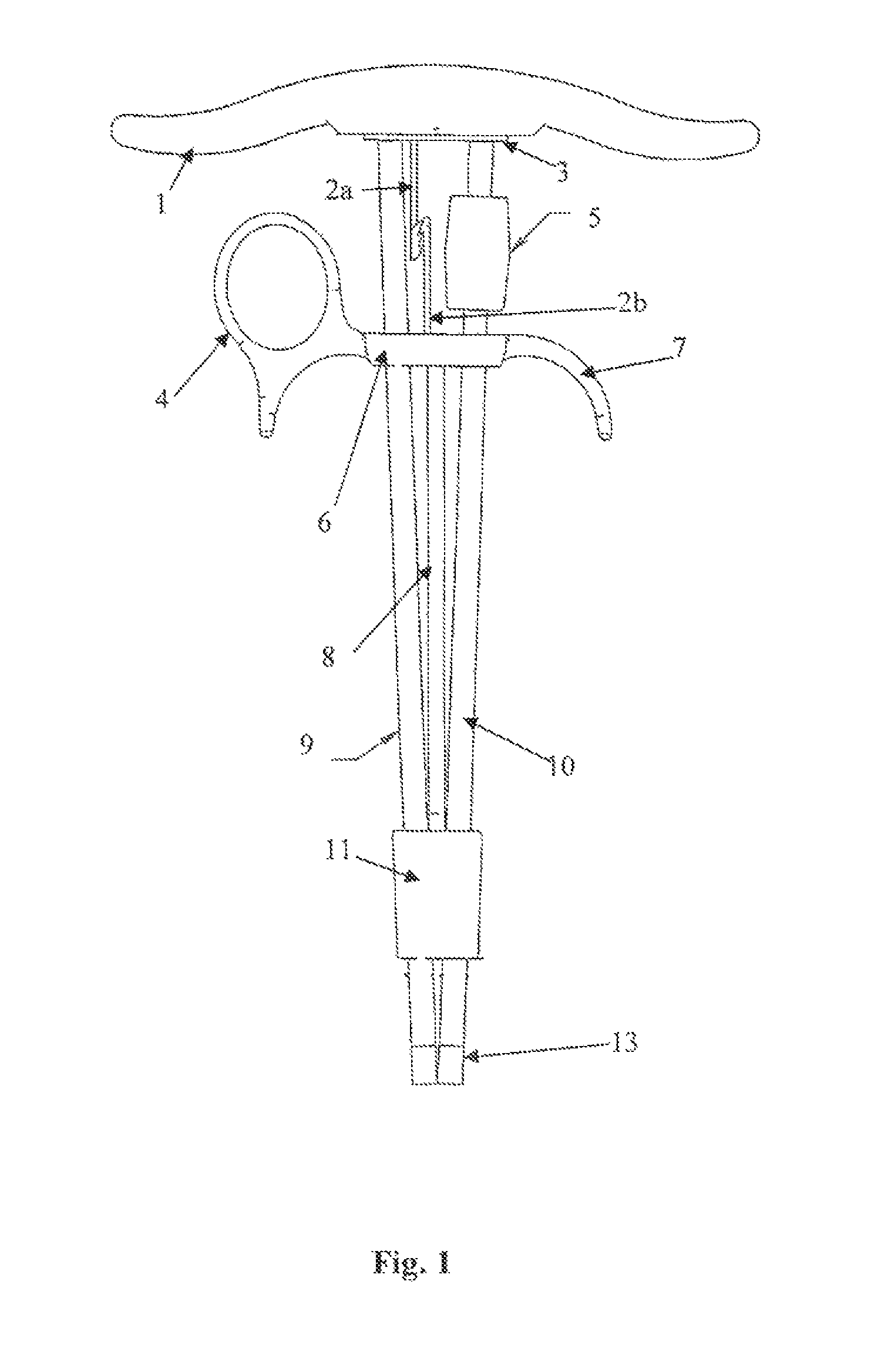
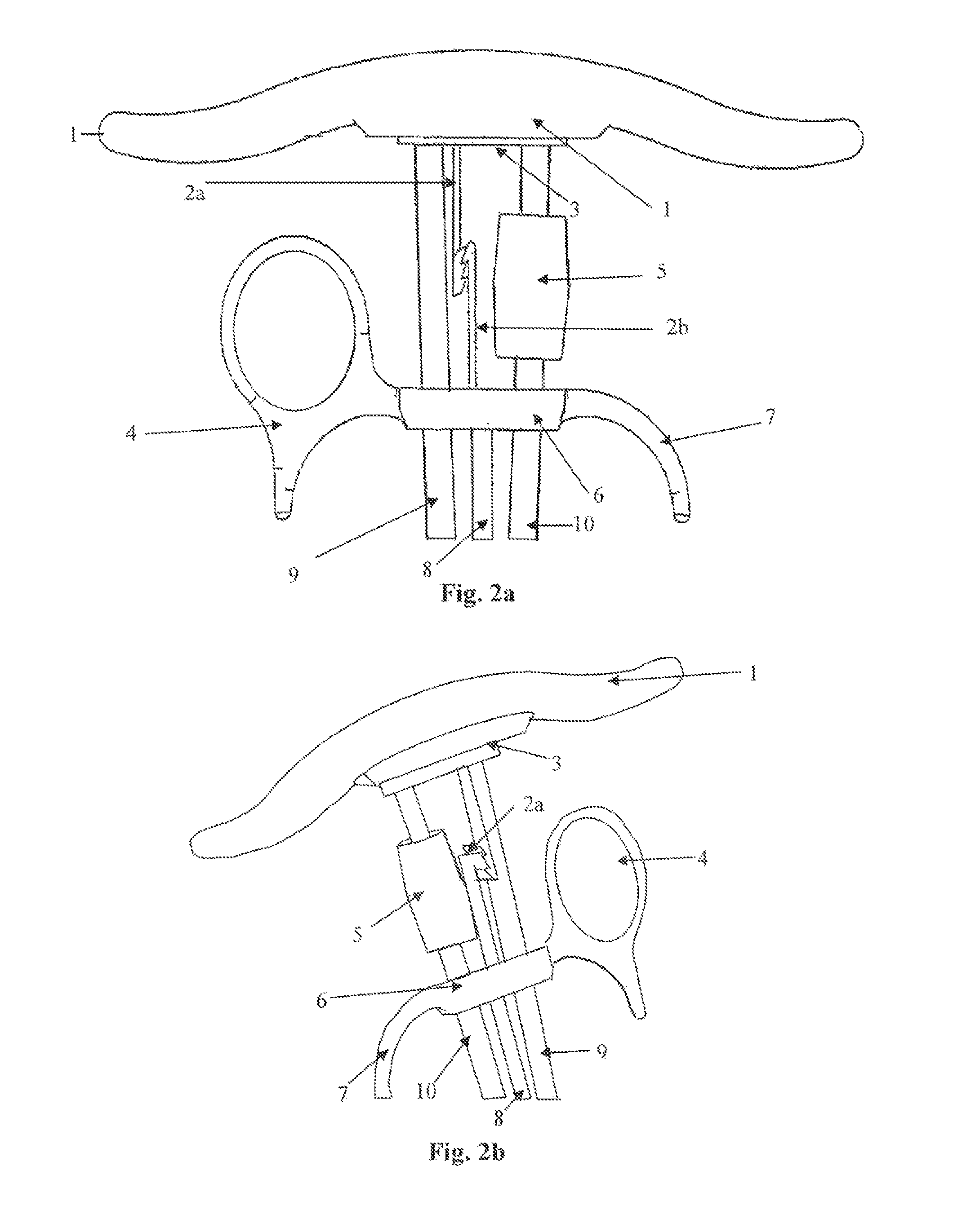
[0038]Turning to the diagram, FIG. 1 shows the rotational driver comprising an interactive portion, wherein each interactive portion comprises a first extended member and a second extended member, such as two rods 9, 10 which approximate to each other resembling a pair of chop-sticks. Each extended member comprises a first distal end, a proximal end and a main extended member body, wherein said main member body in between said distal end and first proximal end, wherein said first distal end comprises a first contact distal end. At the distal end of each rod 9, 10 the surface is fluted creating a needle-grasping portion 13. The proximal ends of the rods 9, 10 have round contours. These rounded ends are embedded in its corresponding sockets located in the handle 1 of the invention. The handle 1 is ergonomically designed to rest against surgeon's palm his hand, permitting its proper use to right and left handed surgeons. The surgeon will maintain the handle 1 fixed to the palm his hand...

fourth embodiment

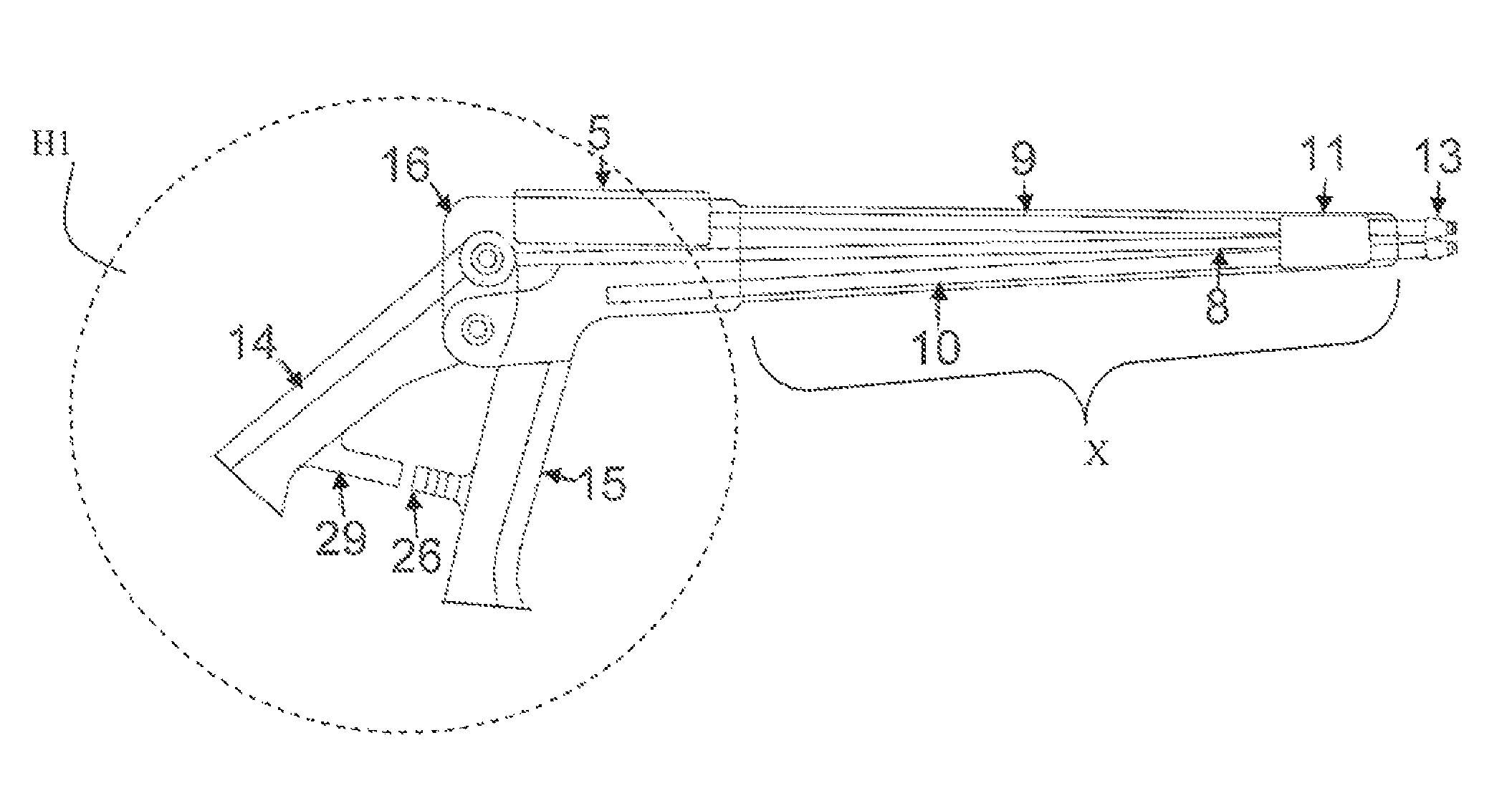
[0045]The forth embodiment rotational actuator 5′ is located close to the handle's movable element 14 and a static element 15 for easy assess for the user after locking the locking mechanisms. Further de distal end 13′ comprises a first distal end 13b′ and a second distal end 13′a, wherein said second distal end contact the first distal end in a oblique manner in order to concentrates the compressing force in a particular point such as the first distal contact 130a and the second contact distal end 130b. The fourth embodiment comprises a linear motion system, wherein said linear system control the displacement of said second distal end 13′b toward the first distal end 13′a for performing a holding or compressing action at the first distal contact 130a and the second contact distal end 130b. The linear system employs said second extended member 10′ to provide the linear motion by means of the movable element 14 at the handle, wherein a compressing action or pulling action toward the ...


PUM


Abstract

A rotational driver that comprises a interactive portion, wherein each interactive portion comprises a first extended member and a second extended member, a rotational system and a linear motion system, wherein the rotational driver permits a left or right handed surgeons to perform the surgical suturing procedure in a less complicated and more secure way by allowing more control over the suturing needle and the area to be stitched, even when the suturing area is small, deep, and / or restricted.

Description

RELATED APPLICATIONS[0001]This application is a continuation in part related to U.S. patent application Ser. No. 11 / 969,660 filed on Jan. 4, 2008 now abandoned.BACKGROUND OF INVENTION[0002]1. Field of the Invention[0003]The present invention relates generally to a surgical suturing device, more specifically, to a ergonomic Rotational Action Needle Driver which enhance the tissue suturing procedure, particularly the one performed on restricted, deep and less accessible locations, by incorporating a pull-locking mechanism that prevents problems associated with loss of needle control during the suturing procedure and the ones associated with prior needle driver's handedness. It also enhances the control surgeons has over the suturing needle by enabling a rotational movement while driving the suturing needle through the tissue that permits to place the needle in the right location in order to continue the subsequent steps of the suturing cycle.[0004]2. Background of the Invention[0005]S...

Claims


Application Information

Patent Timeline
Patent Type & Authority Patents(United States)
IPC IPC(8): A61B17/062A61B19/00A61B17/29A61B17/04A61B17/00
CPCA61B17/062A61B17/0491A61B2017/0042A61B2017/2929A61B2017/2946A61B2019/467A61B2090/067
Inventor ALMODOVAR, LUIS JOSE
Owner ERGOSURGICAL GRP CORP
Why Eureka
Try Eureka