
Dual pitch thread

a dual-pitch thread and thread technology, applied in the direction of threaded fasteners, nuts, fastening means, etc., can solve the problems of affecting the performance of the threaded hole, the risk of missing the screw, and the second kind of threaded holes, so as to reduce the strength, enhance the strength of the two female threads, and reduce the functional strength and durability

Inactive Publication Date: 2015-12-08
POMERANTZ ITZHAK +1
View PDF26 Cites 0 Cited by
  • Summary
  • Abstract
  • Description
  • Claims
  • Application Information

AI Technical Summary

Benefits of technology

[0012]Embodiments of the present invention include a threaded insert that can accommodate two dissimilar screw types and produce a functional assembly with either of them without damaging either screws or the threaded insert itself. Although it is possible to form two female threads for two types of screws in a single hole directly in the bulk of a part, thus enabling both screws to thread into the hole without jamming, the two thread forms will be partial, as they cut into each other. The resulting threaded hole will feature reduced functional strength and durability compared to forming just one of the said threads. In a preferred embodiment the dual pitch threaded insert is produced of appropriate materials and treated so to strengthen and or harden it so to negate the reduction in strength associated with forming two threads in the same hole. In a preferred embodiment common steel hardening alloys and techniques such as through hardening by quenching and tempering, case hardening by carburizing, quenching and tempering and precipitation hardening by artificial aging are used to produce dual pitch threaded inserts featuring enhanced strength of the two female threads in an economical fashion. It is worth noting that some of the above hardening techniques are commonly used in the art of threaded inserts, for example, in order to harden the thread cutting external, male, thread to enable it to cut its own installment thread into metal parts.

Problems solved by technology

This mistake happens commonly when two similar sized screws are available to users.
A miss-matched screw assembly can damage both the screw thread and the threaded hole, depending on the respective material strength.
The second kind of threaded holes is subjected to the risk of miss-matched screws, with varying severity.
The resulting threaded hole will feature reduced functional strength and durability compared to forming just one of the said threads.

Method used


Image

  • Dual pitch thread
  • Dual pitch thread
  • Dual pitch thread

Examples


Embodiment Construction

[0019]The invention summarized above and defined by the claims below will be better understood by referring to the present detailed description. This description is not intended to limit the scope of claims but instead to provide examples of the invention.

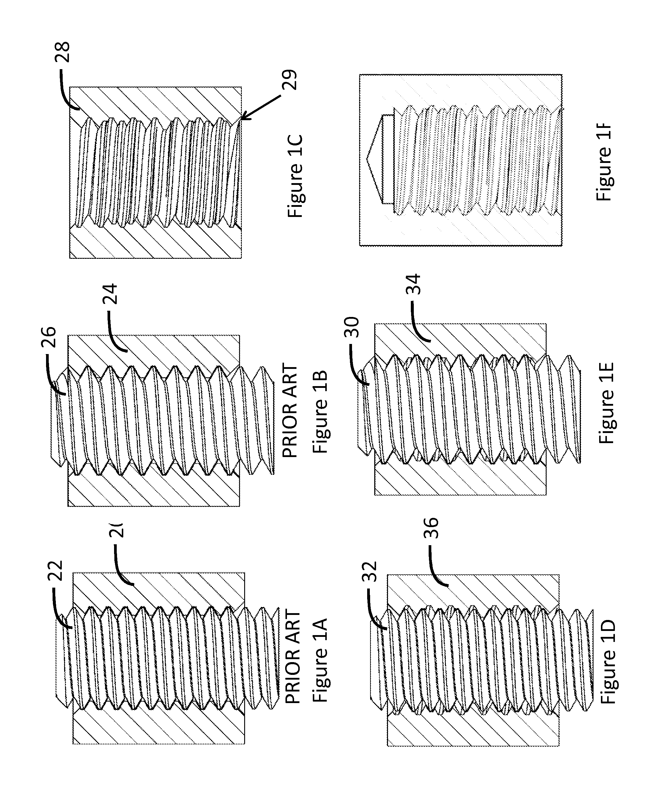
[0020]FIG. 1A shows a cross-section through an object featuring a conventional threaded hole 20 and a matching screw 22 threaded in it.

[0021]FIG. 1B shows a cross-section through an object featuring a similarly sized but different type of threaded hole 24 and a matching screw threaded in it.

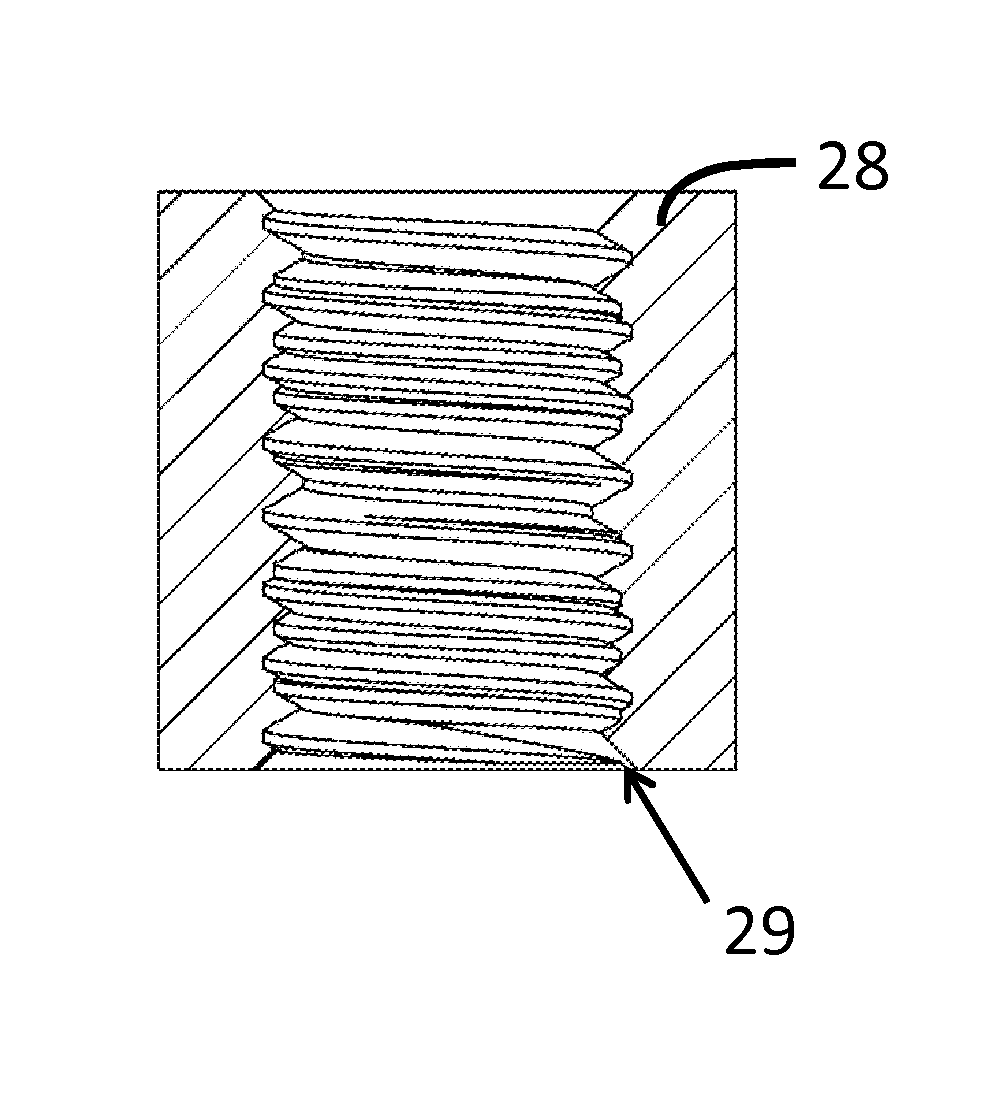
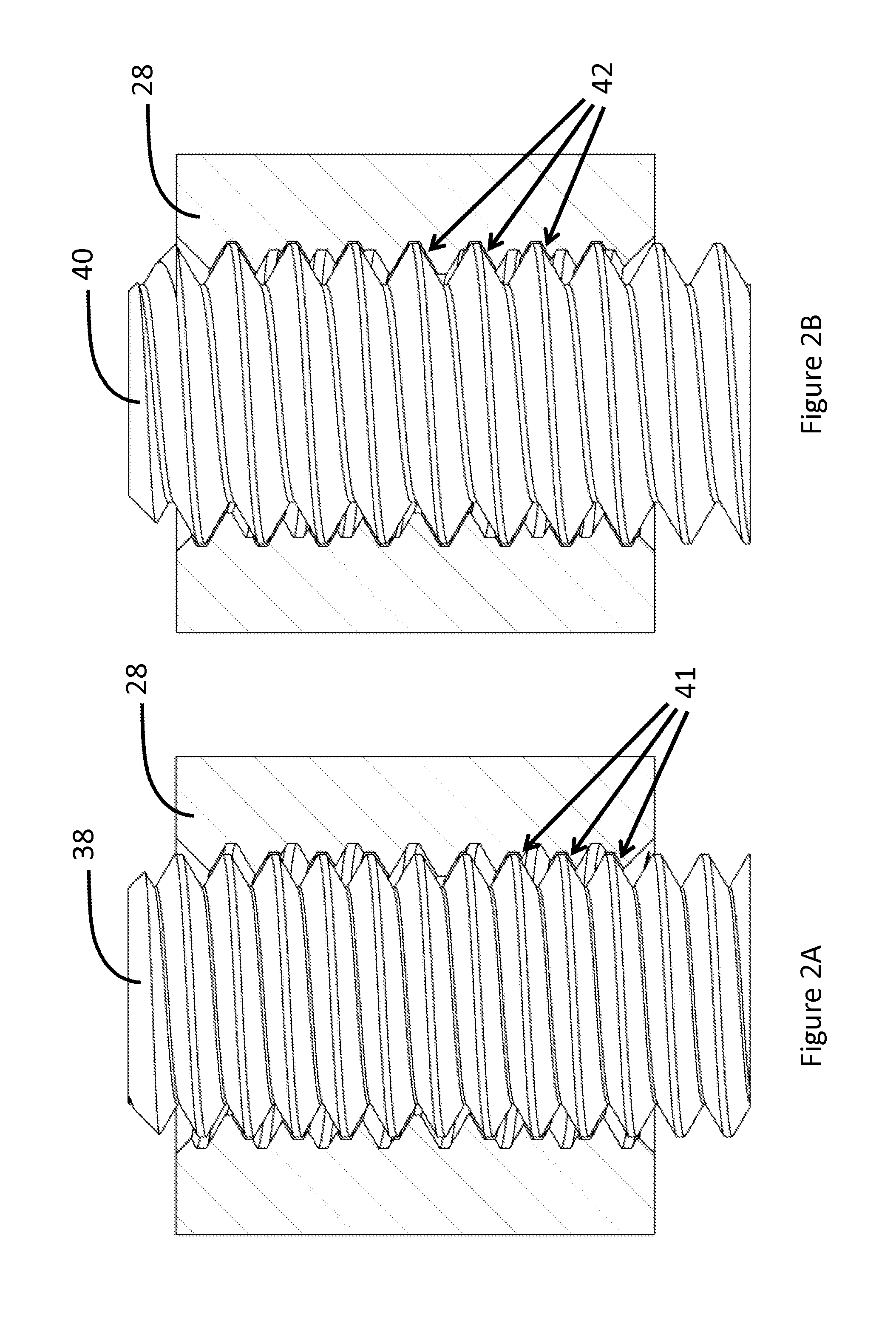
[0022]FIG. 1C shows a cross-section through an object 28 designed according to an embodiment of the present invention. Object 28 can be regarded as having a threaded hole into which both thread types, 20 and 24, are formed thereon.

[0023]In one embodiment of the invention, both threads start at the same point 29 with sufficient accuracy, so that there is only one starting point for both threads into the threaded hole, at least from one, designate...


PUM


Abstract

Disclosed herein is an object that has two threads of different pitches. The two threads overlap and may have a common starting point. The object may be any type of threaded insert, including those commonly referred to as a type of nut or rivet such as a clinch-nut, a weld-nut and a rivet-nut. Also disclosed is a system having a part and the disclosed insert installed onto it. Embodiments of the invention reduce the likelihood of damage when a screw is miss-matched with a similarly sized but different threaded hole.

Description

RELATED APPLICATION[0001]This application claims priority under 35 U.S.C. §119(e) to U.S. Provisional Application No. 61 / 839,661, filed Jun. 26, 2013, which is hereby incorporated by reference in its entirety.BACKGROUND[0002]The following terms are defined for use in the present disclosure:[0003]Screw—meant here as the type known as a machine screw, a type of fastener featuring a male thread of some named standard which is used for mechanical assembly by matching with a suitable threaded hole[0004]Threaded hole—a fastening feature featuring a female thread formed in a hole or bore of some named standard to accommodate a machine screw[0005]A part—any object, fixture or assembly that is designed to be constructed with screws[0006]Threaded insert—an object featuring a threaded hole, which is designed to be installed in a part in order to accommodate a certain type of screw[0007]Through hardening—a process that increases the strength and or hardness of a metal part to its bulk as well a...

Claims


Application Information

Patent Timeline
Patent Type & Authority Patents(United States)
IPC IPC(8): F16B37/16F16B33/02F16B37/12
CPCF16B33/02F16B37/122
Inventor POMERANTZ, ITZHAKPOMERANTZ, URIEL
Owner POMERANTZ ITZHAK
Learn More