
Ferrite core structure for a power supply device of an electric vehicle and power supply road structure using same

a technology of electric vehicles and core structures, applied in the field of ferrite core structures for electric vehicles and power supply road structures, can solve problems such as cracks in the surface of an intermediate portion and road subject to load

Active Publication Date: 2017-01-24
KOREA ADVANCED INST OF SCI & TECH
View PDF6 Cites 0 Cited by
  • Summary
  • Abstract
  • Description
  • Claims
  • Application Information

AI Technical Summary

Benefits of technology

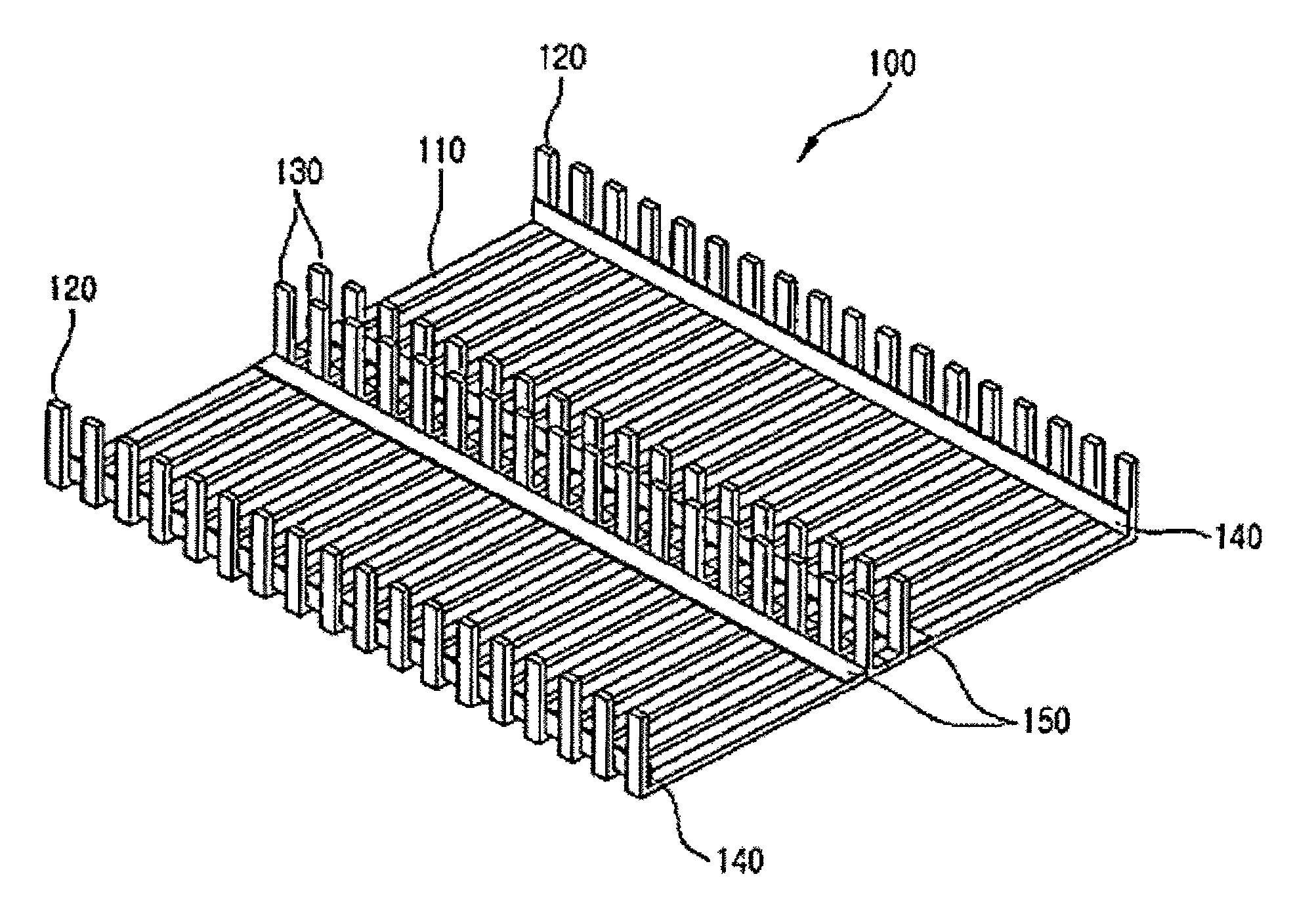
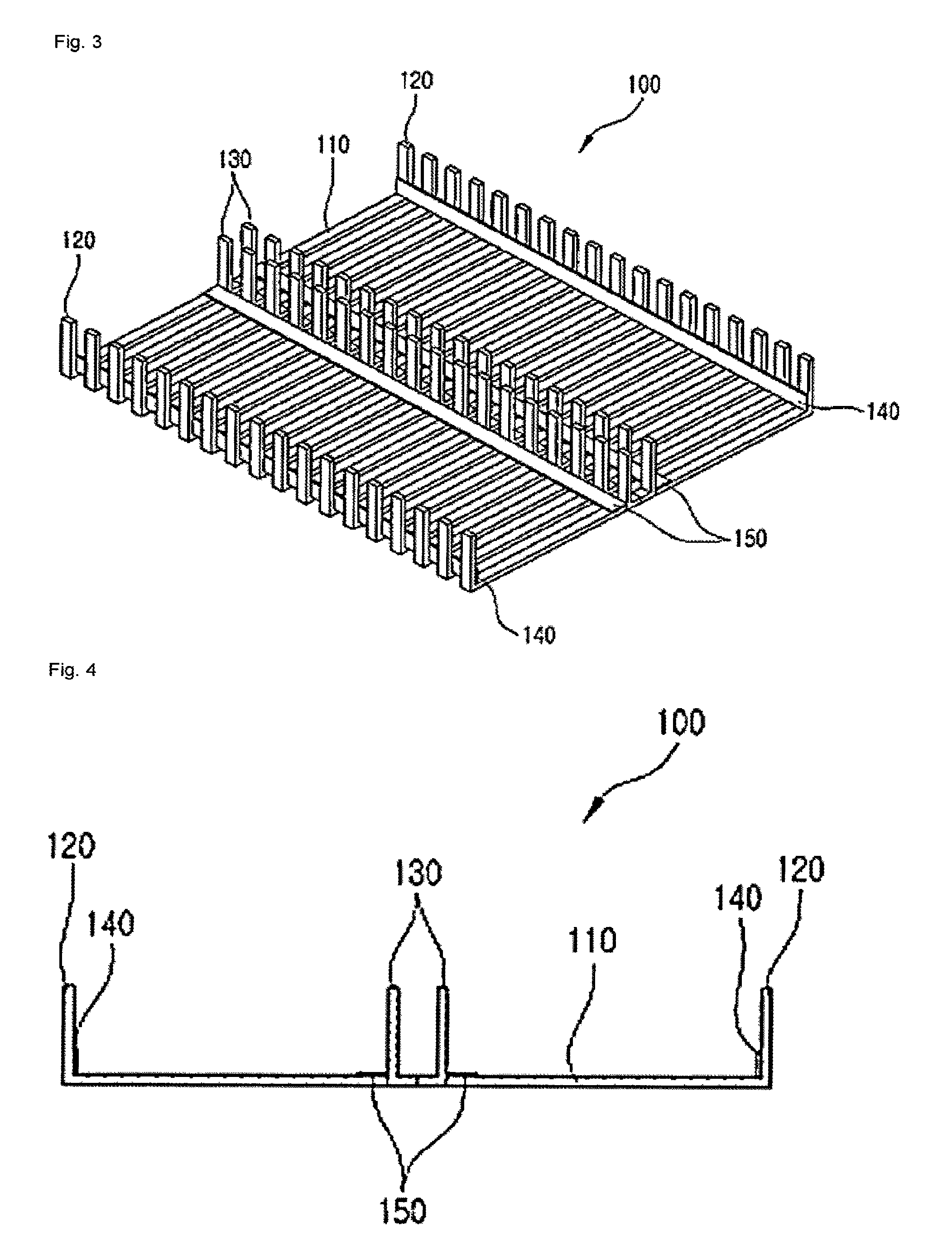
The patent describes a power supply device for electric vehicles that prevents cracks in the surface of the power supply road and improves output compared to conventional modules. It also protects against cracks caused by latent strength reduction due to vehicle travel and load. The device includes a ferrite core structure that reduces warping and increases strength. This can improve the reliability and durability of the power supply device for electric vehicles.

Problems solved by technology

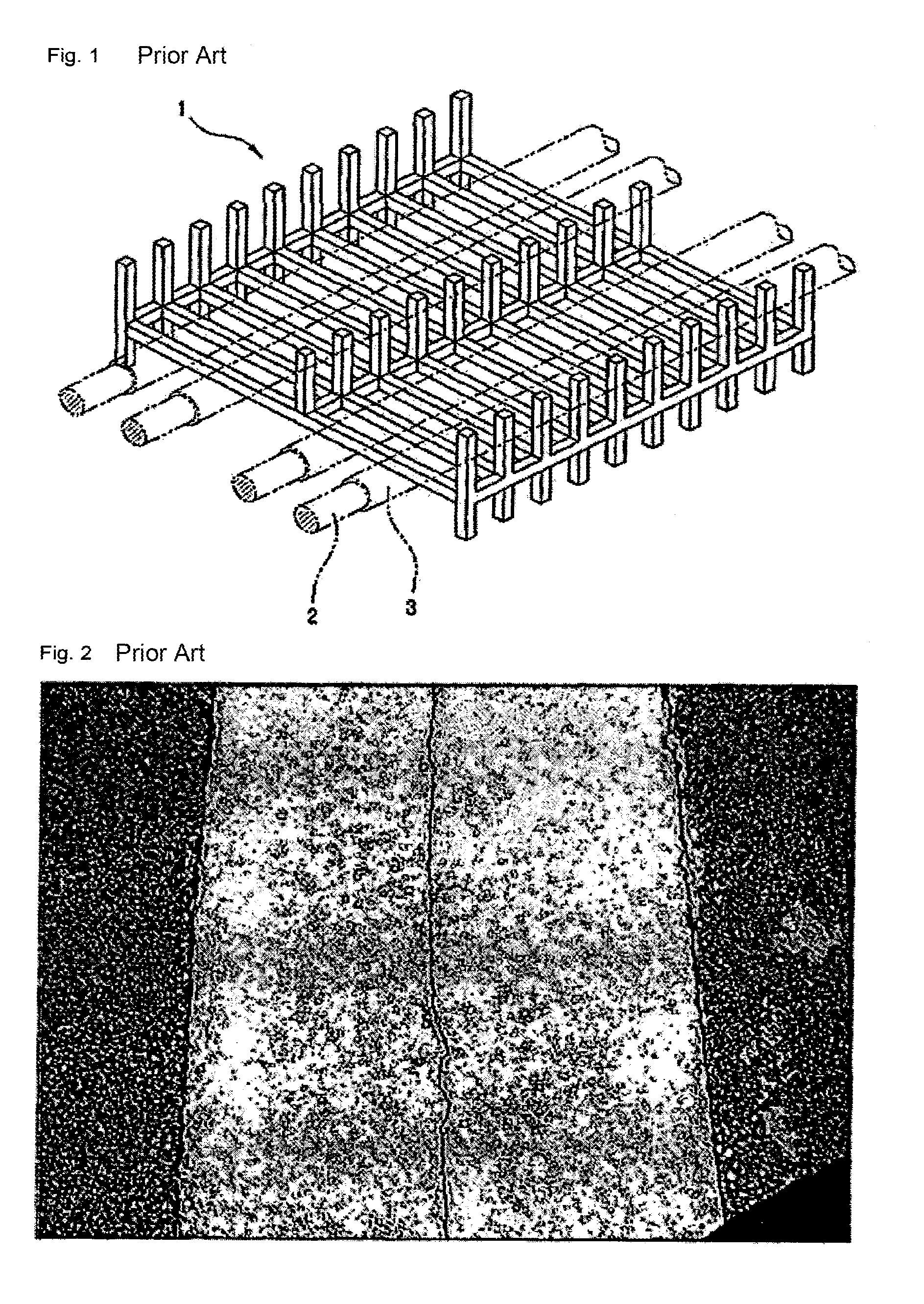
Problems have occurred that cracks were generated in a surface of an intermediate portion of a power supply road due to flexural loading on both sides of each of the vertical core parts.
Another problem of a conventional power supply road is that the road is subject to load repeatedly given by traveling vehicles and have cracks generated by a longitudinal deflection (a traveling direction).

Method used


Image

  • Ferrite core structure for a power supply device of an electric vehicle and power supply road structure using same
  • Ferrite core structure for a power supply device of an electric vehicle and power supply road structure using same
  • Ferrite core structure for a power supply device of an electric vehicle and power supply road structure using same

Examples


Embodiment Construction

Technical Task

[0009]The present invention was in response to the abovementioned needs. The first purpose of the present invention is to provide a ferrite core structure for a power supply device of an electric vehicle which changes the structure of a ferrite core module to prevent cracks generated in a surface of an intermediate portion of a power supply road and improve output more than that for a conventional ferrite core module.

[0010]The second purpose of the present invention is to provide a road structure using a ferrite core structure for a power supply device of an electric vehicle which can prevent cracks from occurring in a road by limiting a reduction in strength due to warpage in a traveling direction by load repeatedly applied to the road due to traveling vehicles.

Means to Solve the Task

[0011]The abovementioned purposes of the present invention can be accomplished by providing a ferrite core structure for a power supply unit of an electric vehicle, which includes multipl...


PUM

PropertyMeasurementUnit
diameteraaaaaaaaaa
currentaaaaaaaaaa
currentaaaaaaaaaa

Abstract

A ferrite core structure for a power supply device of an electric vehicle is disclosed. The ferrite core module improves output and limits a reduction in strength due to warpage in a traveling direction of the vehicle to prevent cracks generated in a surface of an intermediate portion of a power supply road from occurring. The ferrite core structure includes: a plurality of horizontal core parts arranged spaced apart from each other; a plurality of first vertical core parts extending upward from both ends of the horizontal core parts; a second vertical core part having at least two rows extending upward from an intermediate portion of each of the horizontal core parts. The second vertical core part is arranged parallel to the first vertical core parts. A first support part connecting the plurality of first vertical core parts to each other to support the first vertical core parts.

Description

TECHNICAL FIELD[0001]The present invention relates to a ferrite core structure for a power supply device of an electric vehicle and power supply road using same. More particularly, the present invention relates to a ferrite core structure for a power supply device of an electric vehicle which changes the structure of a ferrite core structure according to a related art to prevent cracks generated in a surface of an intermediate portion of a power supply road from occurring and limit a reduction in strength due to warpage in a traveling direction of the vehicle with steel reinforcement in a power supply road in a traveling direction of the vehicle.DESCRIPTION OF RELATED ART[0002]An online electric vehicle is any motor vehicle that can be charged through non-contact electromagnetic field induced from power supply lines laid in the road while it stops or travels. The principles of a transistor holds for the power supply device of an electric vehicle with non-contact electromagnetic indu...

Claims


Application Information

Patent Timeline
Patent Type & Authority Patents(United States)
IPC IPC(8): B60L11/18H01F38/14H01F3/04B60M7/00H01F1/10H01F3/00H01F27/36H02J7/00
CPCH01F38/14B60L11/182B60L11/1837B60M7/00H01F1/10H01F3/04H01F3/00Y02T10/7005Y02T10/7072Y02T90/121Y02T90/122Y02T90/128Y02T90/14B60L53/12B60L53/32Y02T10/70Y02T90/12
Inventor CHO, DONG HOKONG, BYUNG O.SHIN, YOUNG MOOSONG, BO YUNESON, SUNG JUNSHIN, JAE GUE
Owner KOREA ADVANCED INST OF SCI & TECH
Learn More