Control device for shades

a control device and roller shade technology, applied in the direction of door/window protective devices, building components, construction, etc., can solve the problems of affecting the operation of the operator, introducing unnecessary wear and tear to the roller shade mechanism, and other damage to the clutch components

Active Publication Date: 2015-12-15
MANN BILL
View PDF10 Cites 12 Cited by
  • Summary
  • Abstract
  • Description
  • Claims
  • Application Information

AI Technical Summary

Benefits of technology

[0011]The present invention overcomes the disadvantages and shortcomings of the prior art by providing a control device which limits chain stopper collisions with the clutch housing or cover. The present invention provides a device which limits the transfer of forces to the clutch housing, such as resulting from excessive pulling of the chain. Instead, the device redirects forces applied through the chain, particularly through the chain stopper, to a location remote from the housing and clutch assembly.
[0012]A device of the present invention provides a user with an indication of desired chain movement wherein chain movement is limited in one direction upon stopper contact with the device. A chain control device enables a user to manipulate roller shades in a desired manner while limiting threes applied by the chain to the clutch mechanism.
[0013]It is another advantage to provide a chain control device that prevents wear and tear on the clutch or drive mechanisms by tactilely prompting a user to pull the correct side of the chain or cord to effect a desired movement of the shade. The chain control device of the exemplary embodiment utilizes a spring sized to provide a tactile differentiation as the spring is compressed.

Problems solved by technology

Such beaded chains introduce a purely “by chance” event when rotating the chains as there is no way for an operator to know which chain direction is going to produce the desired result.
For example, excessive forces applied to the ball chain can cause the larger chain stopper to crash into the clutch housing and disengage the ball chain or cause other damage to components of the clutch.
In addition to frustrating the operator, pulling the beaded chain in the undesired direction introduces unnecessary wear and tear on the mechanisms of the roller shades, curtain or blinds.
A strong tug on the chain when the roller shade is at full extension, either opened or closed, has the potential of snapping the chain, damaging the housing or clutch, or worse, pulling an entire assembly off of a wall.
Similarly, a tug on the incorrect side of the beaded chain, will cause the beaded chain or the gearing to slip which, over an extended time, will degrade the rotational mechanisms of the blinds.
A beaded chain of the prior art does not provide an operator with the opportunity to learn which chain side to pull because the beaded chain tends to hang in such a manner that the sides of the chain are indistinguishable.
For example, the chain sides often are touching or are wound around each other, and may not be in predictable locations, e.g. to the front or to the back, due to interference with the blinds, furniture, or the window sill.
Further, the typical operator does not have the patience to scrutinize the chain and sprocket (not shown) to determine which side to pull.

Method used


Image

  • Control device for shades
  • Control device for shades
  • Control device for shades

Examples


Embodiment Construction

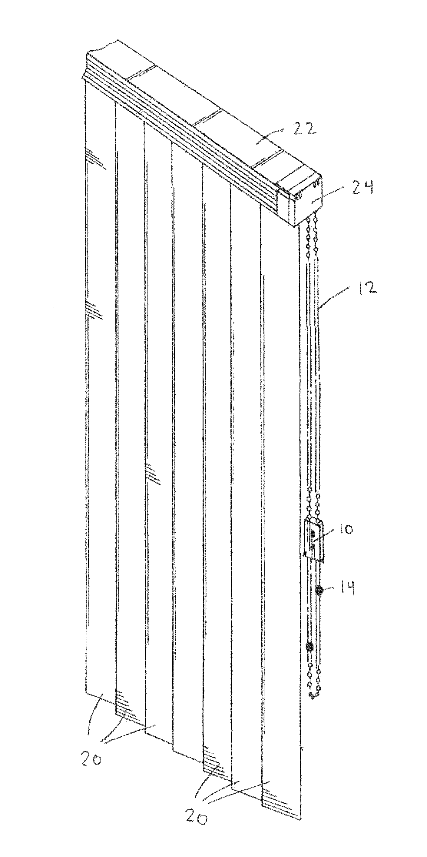
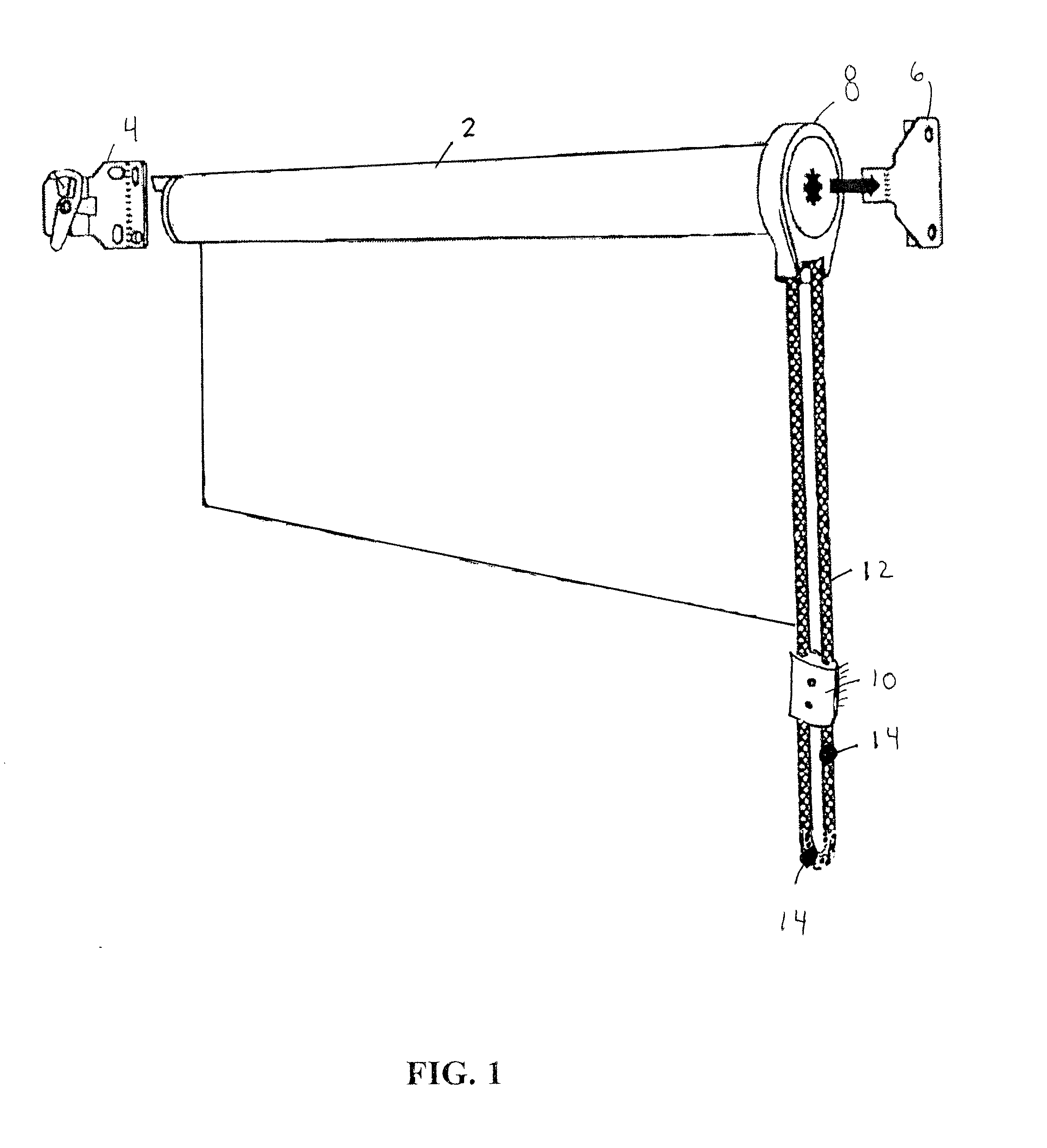
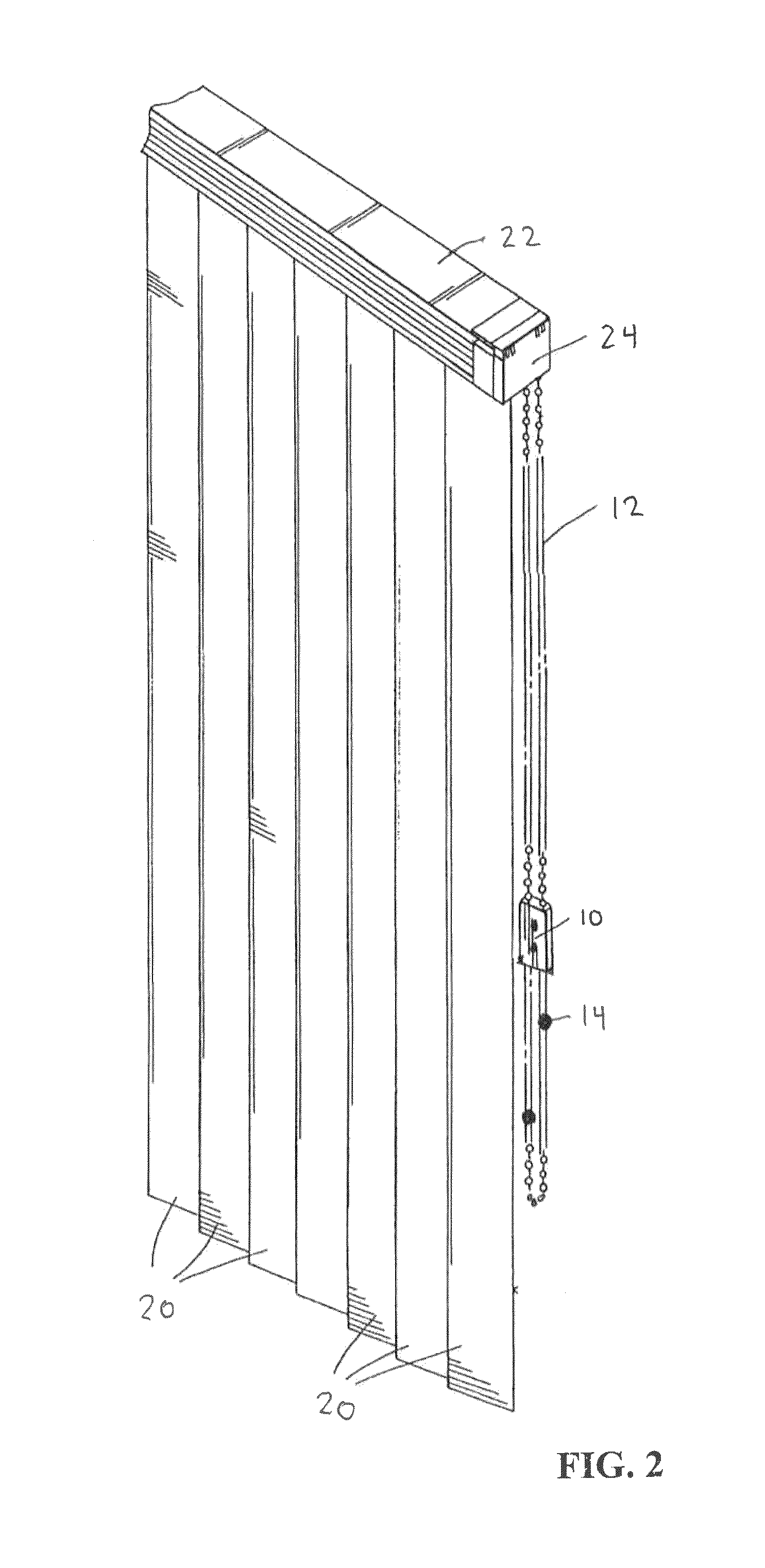
[0030]Referring to FIG. 1, a roller shade 2 is supported by a pair of brackets including a end plug bracket 4 and a clutch bracket 6. A clutch 8 is provided at an end of shade 2 and is supported upon clutch bracket 6. Clutch 8 is engaged to rotate the roller shade into a desired position by a pulling manipulation of chain 12. A control device 10 of the present invention engages chain 12 at a location remote from the clutch 8. Preferably control device 10 is secured to a window frame or molding or nearby wall surface.

[0031]Control device 10 includes a body adapted to receive portion of chain, such as ball chain 12. Other chains, such rope or segmented metal chains may also be used. Ball chain 12 is utilized as described above to control movement of a roller shade 2. Ball chain 12 is provided with stoppers 14, which in this embodiment, are larger ball elements. Ball chain 12 may include multiple ball stoppers to control movement of the roller shade. For example, one ball stopper 14 ma...


PUM


Abstract

A chain control device for inhibiting movement of chains used in window blinds, shades and the like for moving the blinds between operative positions. The chain control device is secured at a location remote from the shades' clutch / drive housing. The chain control device is characterized by redirecting tension forces applied by the user of the blinds away from the shade drive.

Description

RELATED APPLICATIONS[0001]This application claims the benefit of U.S. Provisional Application No. 61 / 798,012 filed Mar. 15, 2013, which application is incorporated by reference.TECHNICAL FIELD[0002]The present invention relates generally to chain control devices for roller shades, curtains or blinds or the like, and more specifically to a chain control device that minimizes jamming and chain disengagement and also prompts a user to move the chain in a direction to effect a desired movement of shades or curtains and within a desired chain tension range.BACKGROUND OF THE INVENTION[0003]Chain operating systems for window blinds are known in the art. They generally include a sprocket or drive wheel for driving a driven blind member such as a drive shaft, a ball chain operatively engaging the sprocket wheel, a cover on the sprocket wheel and a chain stopper on the ball chain. In these systems, the sprocket wheel is drivingly connected to a driven member of a blind. For example, the blind...

Claims


Application Information

Patent Timeline
Patent Type & Authority Patents(United States)
IPC IPC(8): A47H5/032E06B9/324E06B9/44E06B9/50E06B9/78
CPCE06B9/324E06B9/44E06B9/50E06B2009/785
Inventor MANN, BILL
Owner MANN BILL
Why Eureka
Try Eureka