Vane pump

a technology of vane and cam ring, which is applied in the direction of rotary/oscillating piston pump components, machines/engines, liquid fuel engines, etc., can solve the problems of large impact noise and vane to burst to collide, and achieve the effect of reducing noise and clearing between the vane and the cam ring

Inactive Publication Date: 2015-02-24
HITACHI AUTOMOTIVE SYST LTD
View PDF8 Cites 0 Cited by
  • Summary
  • Abstract
  • Description
  • Claims
  • Application Information

AI Technical Summary

Benefits of technology

[0006]The present invention has been made to solve the foregoing problem and it is an object of the present invention to provide a vane pump that can cause a vane to protrude sufficiently even during rotation of a rotor at low speed, to thereby prevent the vane from colliding with an inner periphery of a cam ring and to reduce noise.
[0008]The vane can be made to protrude sufficiently even during rotation of the rotor at low speed. Further, the clearance between the vane and the cam ring is reduced and collision between the vane and the cam ring inner periphery is controlled, so that noise can be reduced.

Problems solved by technology

However, during rotation of the rotor at low speed, the vane protrudes insufficiently due to a small centrifugal force, so that the distal end of the vane may be spaced apart from the inner periphery of the cam ring.
If, at this time, the proximal end of the vane housing slit groove is disposed at the circularly arcuate groove to which the fluid pressure on the discharge side is introduced, a high working fluid pressure on the discharge side flows into the vane housing slit groove to thereby cause the vane to burst to collide with the inner periphery of the cam ring, thus generating a large impact noise.

Method used


Image

  • Vane pump
  • Vane pump
  • Vane pump

Examples


first embodiment

[General Arrangements of Vane Pump]

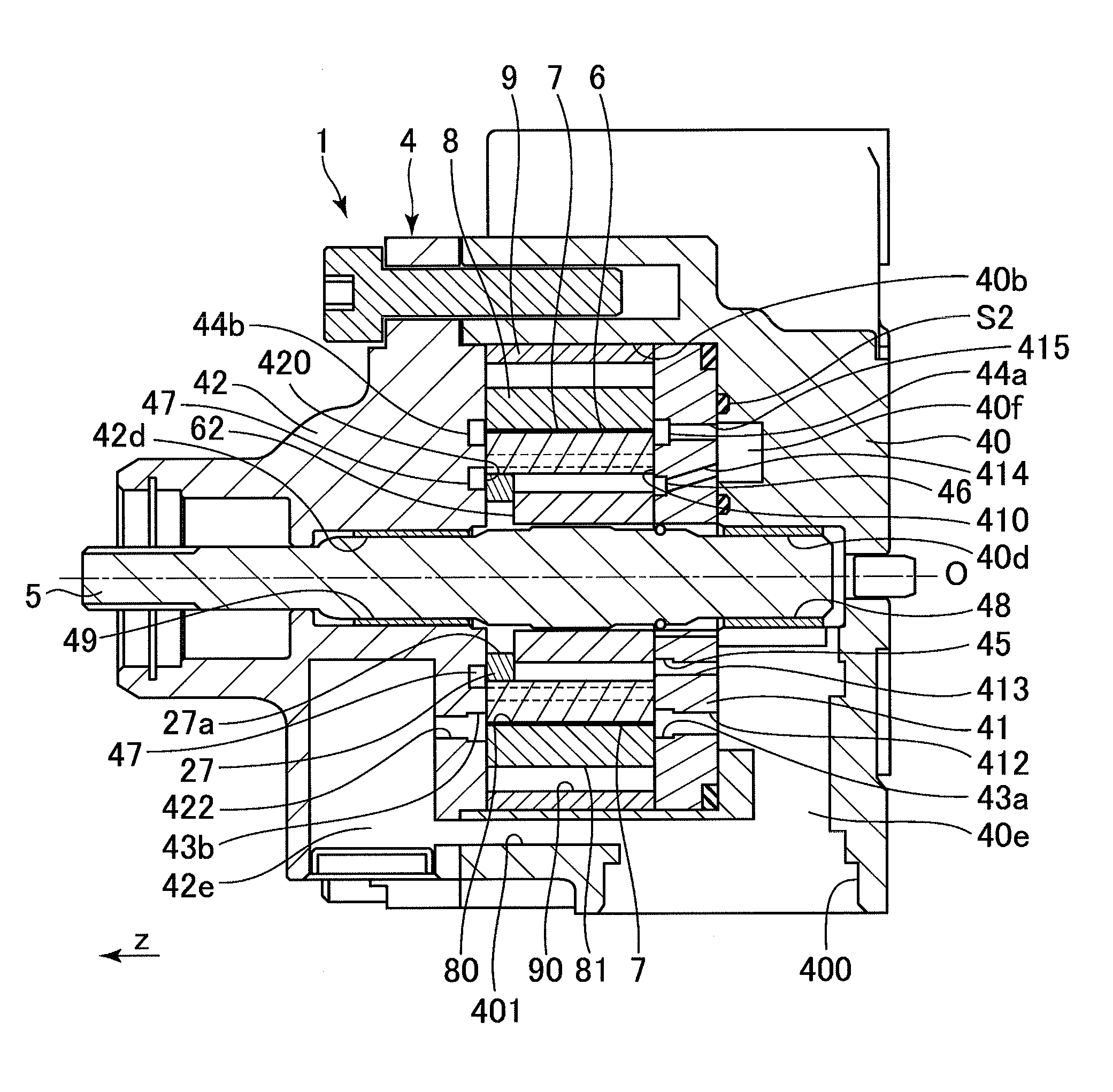
[0021]A vane pump 1 is used as an automotive hydraulic device, specifically, a source for supplying a belt-type continuously variable transmission (CVT 100) with hydraulic pressure.

[0022]The vane pump 1 is driven by a crankshaft of an internal combustion engine and draws a working fluid therein and discharges the working fluid therefrom. A hydraulic fluid, specifically, an automatic transmission fluid (ATF) is used for the working fluid.

[0023]This is, however, not to intend to limit the present invention and the present invention may be applied to a vane pump that supplies any mechanism other than the CVT the hydraulic fluid.

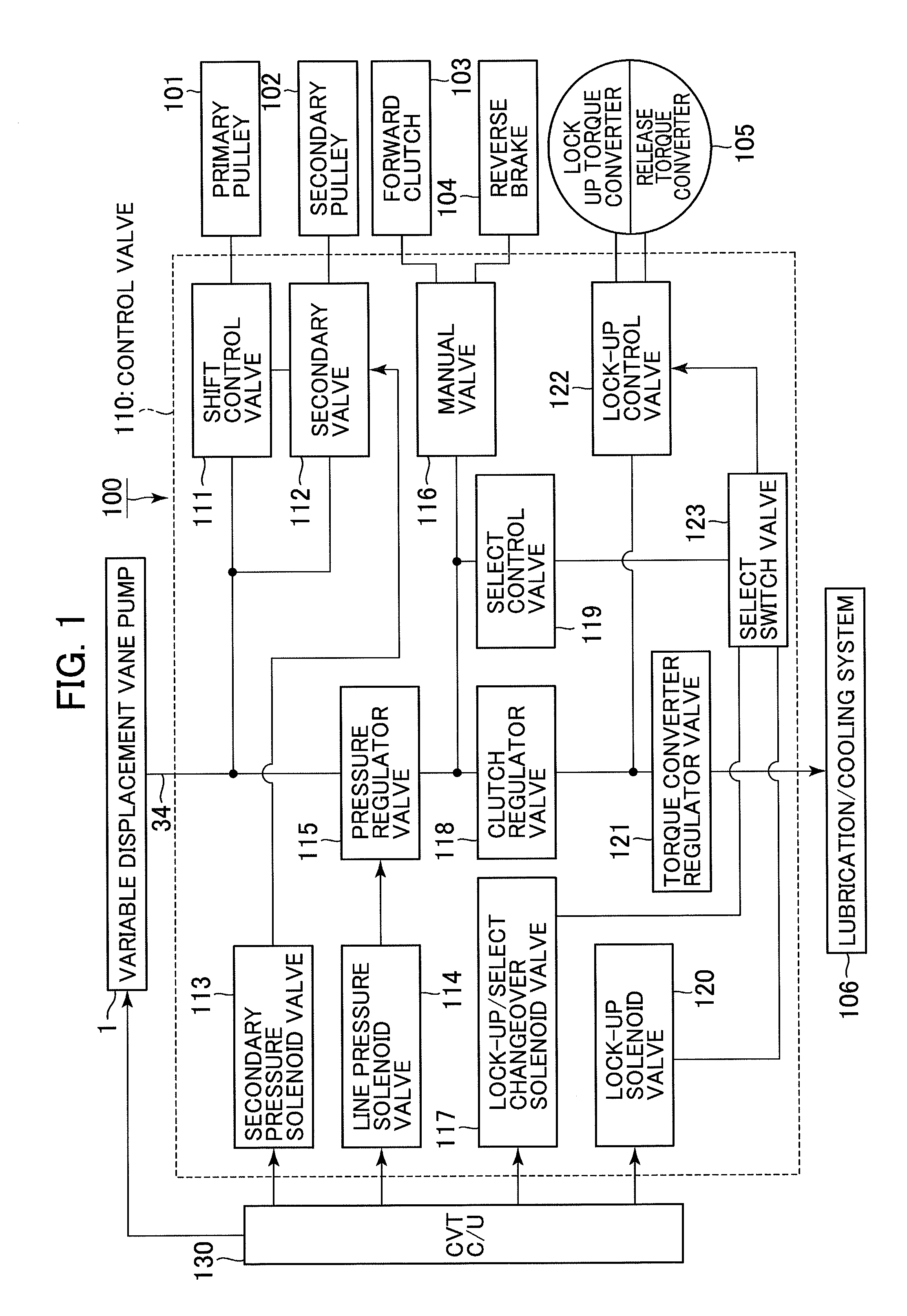
[0024]FIG. 1 is a block diagram showing an exemplary CVT 100. Various types of valves (a shift control valve 111, a secondary valve 112, a secondary pressure solenoid valve 113, a line pressure solenoid valve 114, a pressure regulator valve 115, a manual valve 116, a lock-up / select changeover solenoid valve 117, a clutch regula...

second embodiment

[0172]A vane pump 1 according to a second embodiment of the present invention will be described.

[0173]In the vane pump 1 according to the first embodiment of the present invention, the center of curvature c2 of the curved surface of the vane distal end portion 70 and the center of curvature c1 of the curved surface of the vane proximal end portion 71 are disposed on the side of the vane distal end portion 70 relative to the center in the axial length of the vane 7. In the vane pump 1 according to the second embodiment of the present invention, a center of curvature c2 of a curved surface of a vane distal end portion 70 and a center of curvature c1 of a curved surface of a vane proximal end portion 71 are disposed at the center in an axial length of a vane 7.

[0174]In the description that follows, except for the vane 7, like or corresponding parts are identified by the same reference numerals as those used in the first embodiment of the present invention and descriptions for those par...

third embodiment

[0180]A vane pump 1 according to a third embodiment of the present invention will be described.

[0181]In the vane pump 1 according to the first embodiment of the present invention, the center of curvature c2 of the curved surface of the vane distal end portion 70 and the center of curvature c1 of the curved surface of the vane proximal end portion 71 are disposed on the side of the vane distal end portion 70 relative to the center in the axial length of the vane 7. In the vane pump 1 according to the third embodiment of the present invention, a center of curvature c2 of a curved surface of a vane distal end portion 70 and a center of curvature c1 of a curved surface of a vane proximal end portion 71 are disposed on the side of the vane proximal end portion 71 relative to a center in an axial length of a vane 7.

[0182]In the description that follows, except for the vane 7, like or corresponding parts are identified by the same reference numerals as those used in the first embodiment of...


PUM


Abstract

A vane pump includes a plurality of vanes and a vane cam. Each of the vanes is housed in a corresponding one of multiple slits in an outer periphery of a rotor in a manner of being capable of protruding from, and retracting in, the slit. Each of the vanes has both end faces formed into curved surfaces in a plane perpendicular to a rotational axis of the rotor. The vane cam is disposed in contact with an end portion of the rotor such that an outer peripheral surface thereof contacts inner peripheral side end portions of all vanes to thereby forcedly make the vanes protrude and retract. The vane cam is movable so as to vary an amount of eccentricity relative to a drive shaft.

Description

BACKGROUND OF THE INVENTION[0001]1. Field of the Invention[0002]The present invention relates to a vane pump.[0003]2. Description of Related Art[0004]JP 3631264 B discloses a technique for a vane pump having arrangements in which two circularly arcuate groove portions are formed at portions corresponding to proximal ends of vane housing slit grooves in a rotor and associated with a suction side zone and a discharge side zone of a pump chamber, fluid pressures of the suction side and the discharge side of the pump being introduced to the two groove portions.SUMMARY OF THE INVENTION[0005]In the vane pump disclosed in JP 3631264 B, pressure of a fluid introduced to the circularly arcuate groove and a centrifugal force associated with rotation of the rotor cause the vane to protrude from the vane housing slit groove and a distal end of the vane to abut on an inner periphery of a cam ring. However, during rotation of the rotor at low speed, the vane protrudes insufficiently due to a smal...

Claims


Application Information

Patent Timeline
Patent Type & Authority Patents(United States)
IPC IPC(8): F03C2/00F01C1/00F01C21/08F04C2/00F04C2/344F04C14/22
CPCF04C2/00F01C21/0836F04C2/344F04C14/226
Inventor IIJIMA, MASAAKI
Owner HITACHI AUTOMOTIVE SYST LTD
Why Eureka
Try Eureka