
Eureka
For R&D, Eureka makes reading and utilizing patents & technical documents easy.
Eureka AIR
Designed for self-driven R&D workflows. Generate viable solutions, solve complex R&D challenges, empower your innovation with AI.

Eureka Materials
Designed for material experts only. Revolutionize your material R&D, from search, analyze, to developing new materials.

TechResearch
Generate reliable direction feasibility study reports for your R&D in just a few steps.

TechSeek
Discover and master advanced knowledge NOW. Basics, ideas, possibilities, all at once.

TechMind
As an expert in R&D Theories, TechMind can generates customized viable solutions instantly.

TechRisk
Analyze your overall solution with one click, know your potential R&D risks in advance.

TechMonitor
Get weekly tech updates, stay abreast of the latest tech innovations and key insights.
Resonator, multilayer board and electronic device
a multi-layer board and electronic device technology, applied in the field of resonances, can solve the problems of inability to reduce the noise caused the electric device does not behave properly, and the noise radiated by the multi-layer board itself cannot be reduced, so as to achieve the effect of effective and convenient reduction of parallel plate resonan
- Summary
- Abstract
- Description
- Claims
- Application Information
AI Technical Summary
Benefits of technology
Problems solved by technology
Method used
Image

Examples
first embodiment
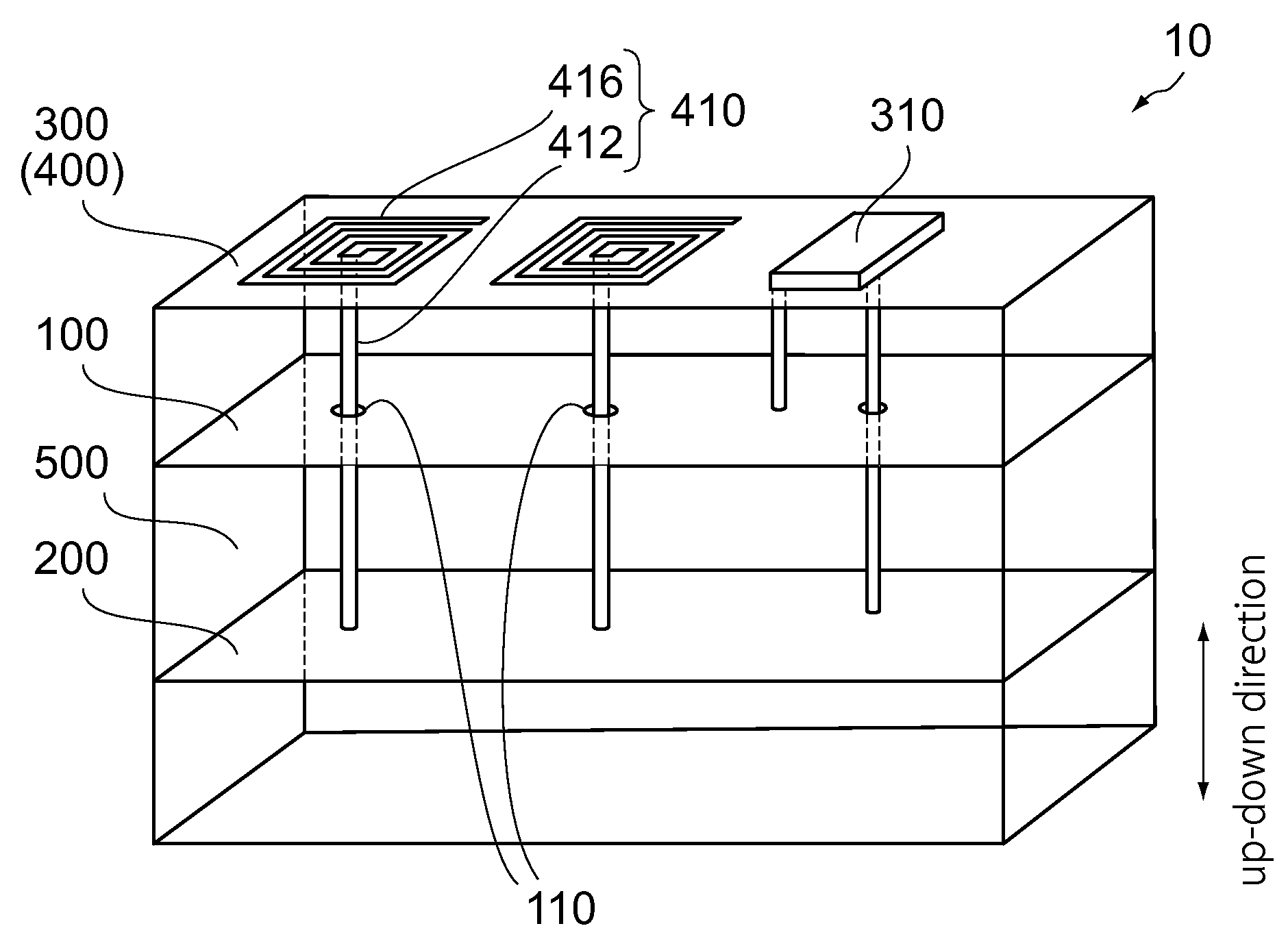
[0023]As shown in FIG. 1, a multilayer board 10 according to a first embodiment of the present invention is formed from insulating bodies (i.e. dielectric bodies) and planes each having a conductive pattern. The insulating bodies and the planes are stacked alternately. The planes are electrically connected with one another, for example, by via holes. The multilayer board 10 is installed and used in an electric device (not shown) such as a personal computer (PC).
[0024]The multilayer board 10 according to the present embodiment comprises one power plane 100, one ground plane 200 and one signal plane 300 as the aforementioned planes. However, the multilayer board 10 may comprise, for example, a plurality of the power planes 100 and / or a plurality of the ground planes 200. When the multilayer board 10 comprises a plurality of the power planes 100, the power planes 100 may be connected with one another. Thus, the multilayer board 10 may comprise at least one power plane 100 (predetermine...
second embodiment
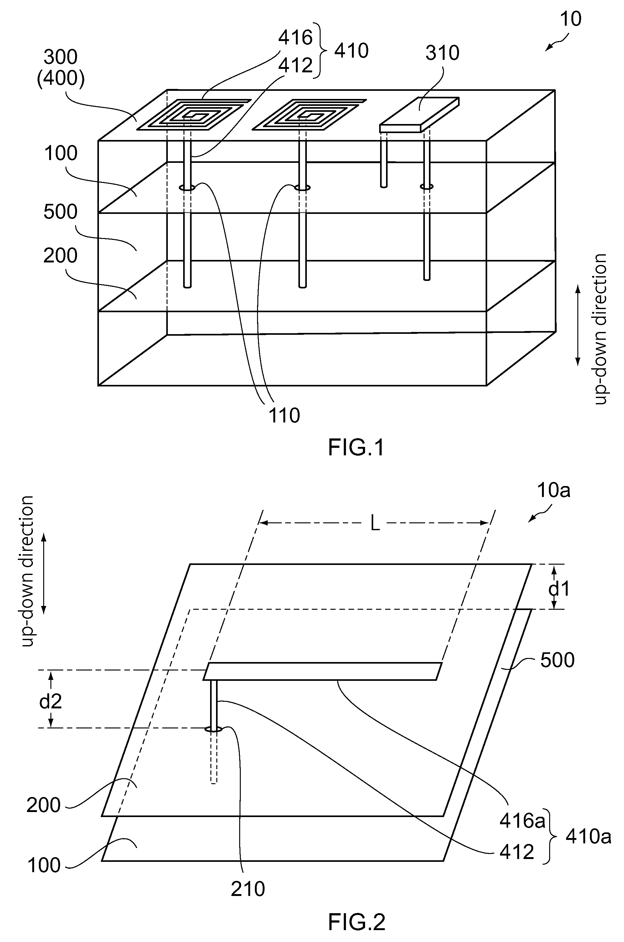
[0037]As shown in FIG. 2, a multilayer board 10a according to a second embodiment of the present invention comprises the power plane 100, the ground plane 200 and the stub plane (not shown). Similar to the first embodiment, the power plane 100 and the ground plane 200 are apart from each other in the up-down direction. Moreover, similar to the first embodiment, the ground plane 200 and the stub plane (not shown) are apart from each other in the up-down direction. In detail, the multilayer board 10a has the dielectric layer 500 formed between the power plane 100 and the ground plane 200. The dielectric layer 500 has a thickness of d1. The multilayer board 10a also has a dielectric layer formed between the ground plane 200 and the stub plane (not shown). The dielectric layer has a thickness of d2. The ground plane 200 is formed with a through hole 210 which pierces the ground plane 200 in the up-down direction. The through hole 210 extends between the power plane 100 and the stub plan...
third embodiment
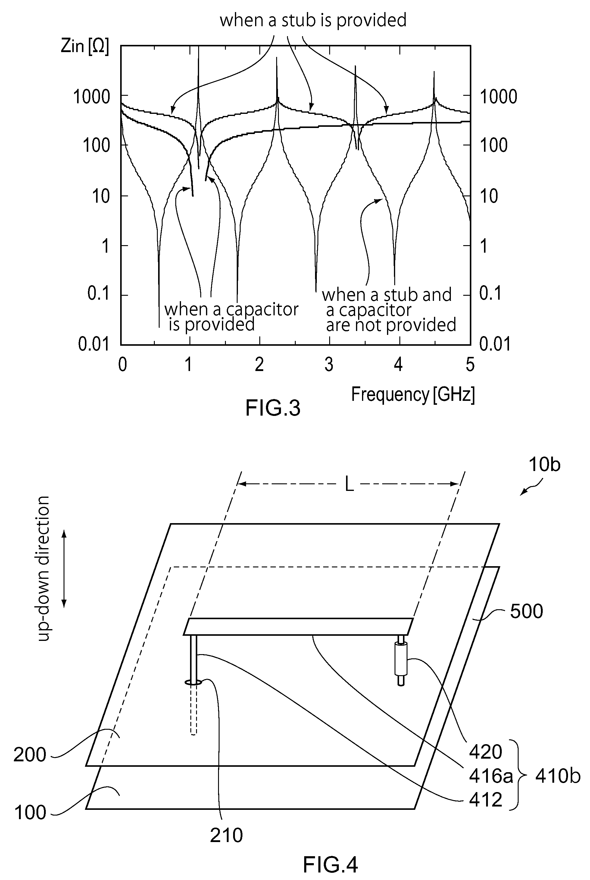
[0046]As shown in FIG. 4, a multilayer board 10b according to a third embodiment of the present invention is configured similar to the multilayer board 10a. However, the multilayer board 10b comprises a stub (resonator) 410b which is slightly different from the stub 410a.
[0047]More specifically, the stub 410b according to the present embodiment includes, in addition to the connecting portion 412 and the body portion 416a, a loss component 420 which attenuates high frequency power while preventing loss of direct-current power. The loss component 420 according to the present embodiment is the resistor 420 connected to the body portion 416a. In other words, the body portion 416a of the stub 410b has the resistor (loss component) 420. In detail, the resistor 420 according to the present embodiment has an end connected to an end of the body portion 416a, and an open end. The resistor 420 has a resistance value which may be designed on the basis of the characteristic impedance of the bod...
PUM
 Abstract
Description
Claims
Application Information
 - R&D Engineer
- R&D Manager
- IP Professional
- Industry Leading Data Capabilities
- Powerful AI technology
- Patent DNA Extraction
Browse by: Latest US Patents, China's latest patents, Technical Efficacy Thesaurus, Application Domain, Technology Topic, Popular Technical Reports.
© 2024 PatSnap. All rights reserved.Legal|Privacy policy|Modern Slavery Act Transparency Statement|Sitemap|About US| Contact US: help@patsnap.com