Implement with telescopically movable stem for stirring or comminuting food

Active Publication Date: 2018-05-03
DELONGHI BRAUN HOUSEHOLD
1 Cites 6 Cited by

AI-Extracted Technical Summary

Problems solved by technology

The resulting processing space that can be reached by the cutter is thus limited.
Furthermore, in the known hand blenders, the stem may adhere by suction to the bottom of the container over and over again during processing, which may be extremely bothersome to the user since an increased amount of force is required to get the stem off the bottom again.
However, the means for displacing the shaft which are required for this are extremely complicated mechanically and thus very expensive.
In addition, the user cannot himself determine the position of the blade in relation to th...

Method used

[0043]Since the requirements for coaxiality of the shaft coupling are high, centring ribs 15 are attached in the upper portion of the inner assembly 2 by way of a centring means and said centring ribs “pre-centre” the shaft radially within a narrow interval. This is helpful to facilitate “threading” the shaft coupling (not shown) on the motor housing onto the shaft coupling 13 of the stem. In the interests of functional integration, these centring ribs 15 also form the abutment surface of the axial bearing 11. Power transmission from the axial bearing 11 onto the shaft 1 is effected via a U-shaped washer 16 and a rolling on the shaft 1 (see FIGS. 3a and 3b), which thus represent means for axially locking the shaft below the bearing. The rolling results in a constriction on the shaft and a bulge 17 in front of and behind the material displaced by the constriction that projects above the shaft diameter. This means that it no longer fits through the relatively close-fitting U-shaped washer. The shaft 1 is additionally axially fixed in the inner assembly 2 by a further safety washer 18 on the shaft 1 above the centring ribs 15 of the inner assembly 2. The outer assembly 3 further also comprises a shaft seal 5 (FIG. 2), to reduce contamination from wetting of the shaft.
[0044]The bearing of the two assemblies 2 and 3 required for mutual axial displacement is provided at two places by slide bearings 6, 6′ of simple geometry, wherein the half of the slide bearing provided at the lower end of the inner assembly 2 is represented by a broadening 6 that partially protrudes above the circumference and the opposite half of the slide bearing is represented by a cylindrical slide sleeve attached to the inside of the outer assembly 3. At the top end of the inner assembly 2, however, there can be provided projections 6′ that are distributed around the circumference and are supported against a smooth bearing surface on the inside of the top portion of the outer assembly 3. Two different designs of these slide bearing projections 6′ and 6″ are shown in FIGS. 4a) and 4b). A possible slide pairing is between two different plastics, the other possible slide pairing between plastic and metal (e.g. stainless steel). The bearing points 6, 6′ (6, 6″) are attached as far apart as the construction space allows, in order to prevent a self-locking effect in use.
[0045]In the construction described above, the position of the cutter 21 in the starting position is further up than the usual position (away from the container base) (FIG. 5a), in order to reduce suction on the container base and also, due to the division, the stem allows an axial movement of the cutter 21 towards the container base against the force of the spring 4. If, during operation, the user presses axially on the motor housing that simultaneously serves as a handle and is connected to the inner assembly 2, then the mounted shaft is able to transfer this travel through the inner assembly 2 via the shaft 1 mounted in it in an axially o manner to the cutter. During this process, the external geometry of the outer assembly 3 can remain unchanged. To this end, the inner assembly 2 plunges a certain distance into the outer assembly 3 (FIG. 5b) until there the inner assembly 2 comes up against a defined limit stop formed by the int...

Benefits of technology

[0027]Due to its extension, the milling edge protruding axially out of the cutter is not oriented substantially along a tangent to the rotational direction of the cutter, as in the folded elements of the prior art, that is to say with an attack direction oriented substantially perpendicular to the rotational direction, but has attack directions, at least in regions along its extension, which form a sharp angle (“angle of attack”) of 45° or less, preferably 35° or less, to the rotational direction. In the field of cutting blades, direction of attack is understood to mean the normal on the striking edge or striking surface, that is to say the direction in which the striking edge (cutting edge) of a blade meets the material being cut, for example the angle between the direction of attack and the direction of rotation of a radially running edge is 0°. In the milling rib, the striking surface is the side face of the milling rib pointing in the rotational plane. The milling edge preferably has an attack angle of 45° or less, particularly preferably 35° or less, along its entire extension.
[0028]In the present case, a cutting edge is understood to be a horizontally cutting edge of the cutter, which is therefore able to make cuts in the rotational plane. The cutting edge is created in that the blade metal is deep drawn at a (deep drawing) angle of 20°, for example, and then sharpened by grinding. The grinding is done in the rotational plane of the blade, so that the said angle therefore determines the so-called wedge angle of the blade, that is to say the angle between the rotational plane and a (top or bottom) surface of the cutting edge.
[0029]The axial direction is a direction perpendicular to the rotational plane of the cutter. Within the meaning of the present invention, the hub is that region of the blade which receives the shaft in a receiver, so, for example, comprises an opening or mounting option for inserting and fastening the shaft, and also the region immediately surrounding the receiver, which is necessary for the structural strength of the connection of driveshaft to blade/cutter. In the known blades, this region is mostly a circular area, from which the cutter or cutters extend substantially radially but, according to the present invention, can also have geometries that differ from the circular form.
[0030]This blade arrangement extends the functionality of the blade in a very advantageous manner and improves, in particular, the effects of the displaceability of the cutter in accordance with the invention. In addition to cutting with the sharp cutting edges of the cutter of the blade in the circumferential direction, there is also an effective milling functionality of the milling rib in the compression direction. This in turn enables the cutter to cut solid food more effectively and more quickly. The effect of the blade arrangement according to the invention is based on the fact...

Abstract

An implement for stirring or comminuting, containing a drive motor arranged in a motor housing, a stem, in which a shaft connected to the drive motor in a rotationally rigid manner is mounted, and which is divided into an inner and an outer assembly, wherein the outer assembly has a shield at an end remote from the motor housing, and a working part surrounded by the shield, wherein the shaft is guided in an axially immovable manner in the inner assembly and the inner assembly is axially movable relative to the outer assembly. The working part is fixedly connected to the stem and is mounted in an axially immovable manner in the inner assembly, such that the working part can move in relation to the shield.

Application Domain

Transportation and packagingRotary stirring mixers +2

Technology Topic

Drive motorEngineering

Image

  • Implement with telescopically movable stem for stirring or comminuting food
  • Implement with telescopically movable stem for stirring or comminuting food
  • Implement with telescopically movable stem for stirring or comminuting food

Examples

  • Experimental program(1)

Example

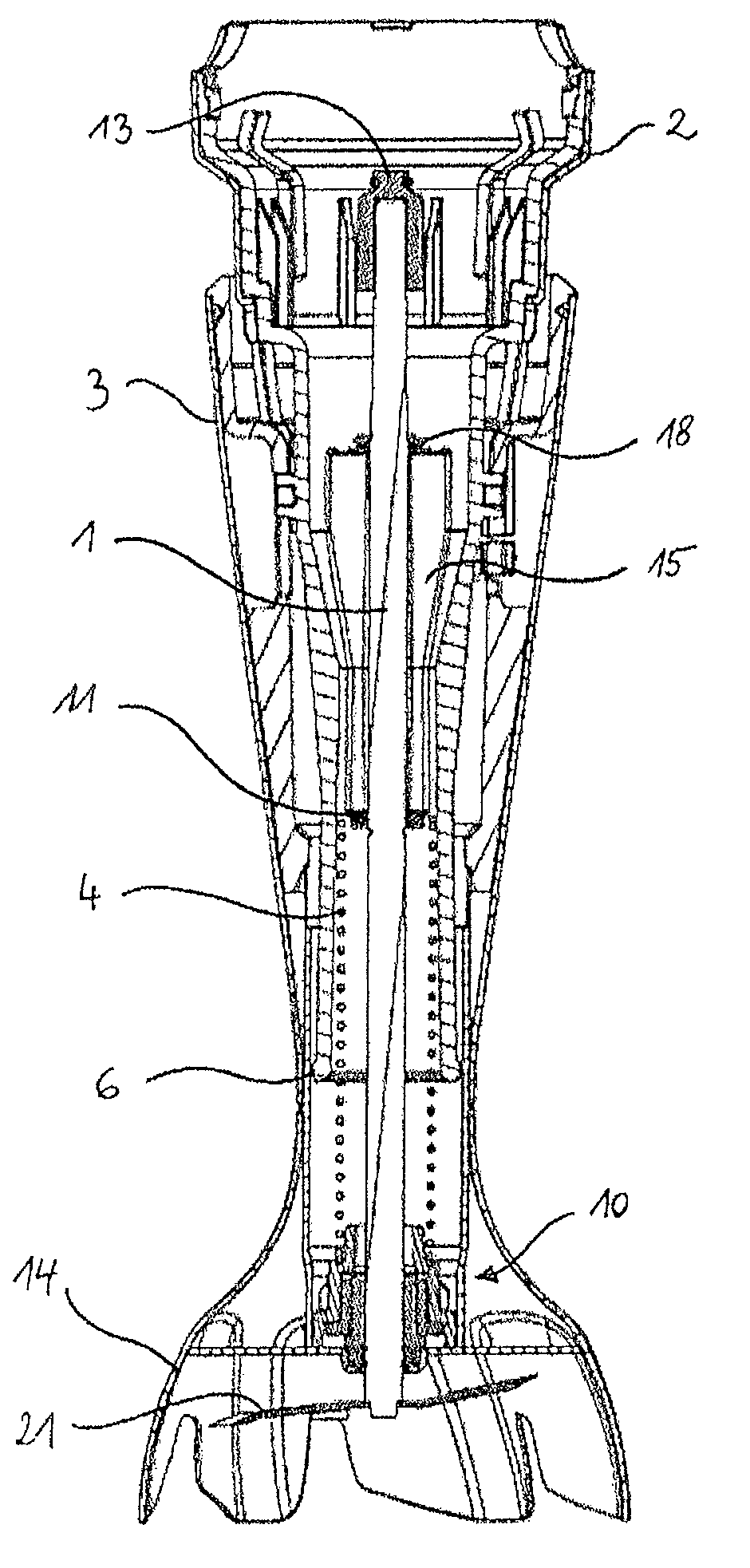
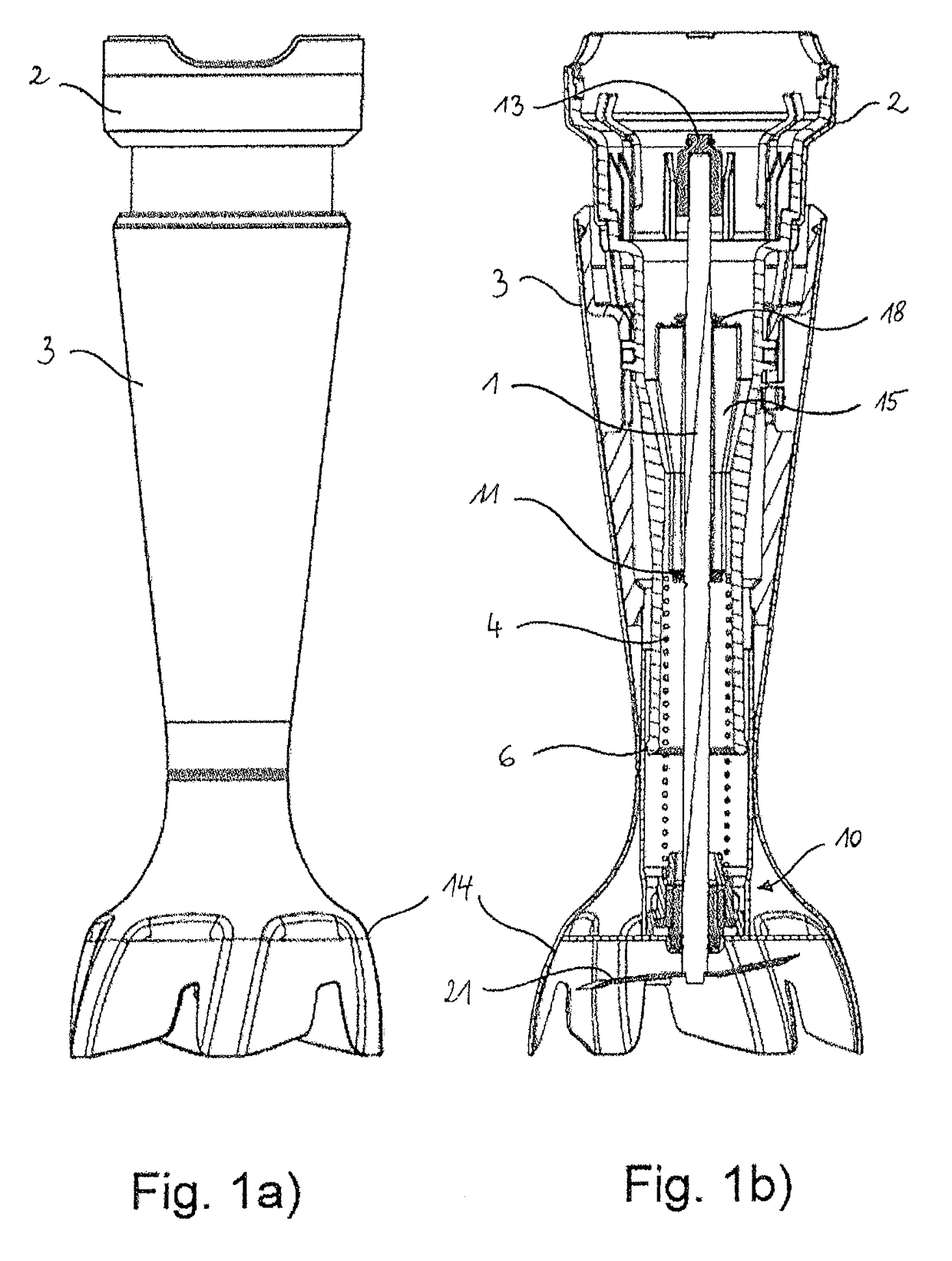
[0040]FIG. 1a) shows a lateral view of the stem of an implement according to the invention, in this example a hand blender. The stem is divided into an inner assembly 2 and an outer assembly 3. The inner assembly 2 is capable of moving telescopically into and out of the outer assembly 3. As can be seen in the longitudinal sectional view of the stem in FIG. 1b), the shaft 1 is guided in the inner assembly 2 and is supported therein by means of an axial bearing 11. In addition, the inner assembly 2 is configured so that it can be detachably coupled with the hand blender motor housing (not shown here), which simultaneously forms the handle for the user, wherein no relative movement is allowed between motor housing and inner stem assembly 2 in the coupled state. This also connects the shaft 1 with the motor shaft via the shaft coupling 13.
[0041]At the lower end of the outer assembly 3 there is a bell-shaped shield 14 for the cutter 21 (working part) attached to the bottom end of the shaft 1, said cutter being preferably completely surrounded by the shield (bell) 14. On the inside, the shield has a cover plate 12, which, together with the shield 14, forms a processing space that is sealed off from the outer assembly 3. Furthermore, in the outer assembly there is a radial slide bearing 7 in close proximity to the cutter 21, since it is here that the torque is at its greatest. Here, the radial slide bearing 7 is provided on the cover plate 12 of the shield 14, since this component is closest to the cutter 21. The radial slide bearing 7 is mounted in a flexible collar bushing 8, which is surrounded by a bearing sleeve 9, which fixes the bushing 8 and the radial slide bearing 7 on the cover plate 12. Radial slide bearing 7, collar bushing 8 and bearing sleeve 9 form a bearing assembly 10 (see FIG. 2). The flexible collar bushing 8 allows a slight rotation of the radial slide bearing 7 around an imaginary fulcrum in the centre. If the motor portion (not shown here) is put onto the shaft, the shaft 1 is pushed coaxially to the motor shaft in the upper region via the shaft coupling. Due to manufacturing-related tolerances or an eccentricity of the motor with respect to the adaption, a “rigidly” clamped shaft without flexible collar bushing would easily bend out of shape. In turn this would lead to increased wear of the bearing and a greater amount of noise during operation. The “soft” bearing with the aid of the flexible collar bushing 8 serves as a remedy in this case and the bearing assembly 10 with collar bushing 8 is therefore capable of compensating for normal manufacturing tolerances or the forces due to an eccentrically coupled motor.
[0042]A spring 4 located on the inside in the inner assembly 2 is supported at the bottom by means of a bearing assembly 10 with the radial slide bearing 7 on the outer assembly 3 (FIG. 2) and at the top abuts the inside of the inner assembly 2, so that it forces the two assemblies into a default position, in which the inner assembly 2 is pushed out of the outer assembly 3 at the top, thereby bringing the cutter 21 into its topmost position in the processing space (see FIG. 5a). The bearing assembly 10 is thereby held in position by the spring 4 pressing on the bearing sleeve 9. The limit stops for this travel are attached on the inside of the outer assembly 3 in the form of four longitudinal grooves 19 (longitudinal guides) distributed over the circumference. Ribs 20 (guide elements) attached on the outside of the inner assembly 2 run in said grooves. The four ribs 20, two of which can be seen in FIGS. 5a) and 5b), perform two functions and are divided into two opposing pairs. The one pair determines the end position of the inner assembly 2 in the default position imposed by the spring 4 and also serves for one-off latching behind during mounting of the assembly. The second pair of ribs prevents the inner assembly from twisting relative to the outer assembly (“misuse”). In an alternative (not shown), only two longitudinal grooves are provided on the inside of the outer assembly and accordingly two ribs on the outside of the inner assembly, one longitudinal groove-rib combination determining the axial limit position of the inner assembly and the other longitudinal groove-rib combination preventing mutual twisting of the two assemblies.
[0043]Since the requirements for coaxiality of the shaft coupling are high, centring ribs 15 are attached in the upper portion of the inner assembly 2 by way of a centring means and said centring ribs “pre-centre” the shaft radially within a narrow interval. This is helpful to facilitate “threading” the shaft coupling (not shown) on the motor housing onto the shaft coupling 13 of the stem. In the interests of functional integration, these centring ribs 15 also form the abutment surface of the axial bearing 11. Power transmission from the axial bearing 11 onto the shaft 1 is effected via a U-shaped washer 16 and a rolling on the shaft 1 (see FIGS. 3a and 3b), which thus represent means for axially locking the shaft below the bearing. The rolling results in a constriction on the shaft and a bulge 17 in front of and behind the material displaced by the constriction that projects above the shaft diameter. This means that it no longer fits through the relatively close-fitting U-shaped washer. The shaft 1 is additionally axially fixed in the inner assembly 2 by a further safety washer 18 on the shaft 1 above the centring ribs 15 of the inner assembly 2. The outer assembly 3 further also comprises a shaft seal 5 (FIG. 2), to reduce contamination from wetting of the shaft.
[0044]The bearing of the two assemblies 2 and 3 required for mutual axial displacement is provided at two places by slide bearings 6, 6′ of simple geometry, wherein the half of the slide bearing provided at the lower end of the inner assembly 2 is represented by a broadening 6 that partially protrudes above the circumference and the opposite half of the slide bearing is represented by a cylindrical slide sleeve attached to the inside of the outer assembly 3. At the top end of the inner assembly 2, however, there can be provided projections 6′ that are distributed around the circumference and are supported against a smooth bearing surface on the inside of the top portion of the outer assembly 3. Two different designs of these slide bearing projections 6′ and 6″ are shown in FIGS. 4a) and 4b). A possible slide pairing is between two different plastics, the other possible slide pairing between plastic and metal (e.g. stainless steel). The bearing points 6, 6′ (6, 6″) are attached as far apart as the construction space allows, in order to prevent a self-locking effect in use.
[0045]In the construction described above, the position of the cutter 21 in the starting position is further up than the usual position (away from the container base) (FIG. 5a), in order to reduce suction on the container base and also, due to the division, the stem allows an axial movement of the cutter 21 towards the container base against the force of the spring 4. If, during operation, the user presses axially on the motor housing that simultaneously serves as a handle and is connected to the inner assembly 2, then the mounted shaft is able to transfer this travel through the inner assembly 2 via the shaft 1 mounted in it in an axially o manner to the cutter. During this process, the external geometry of the outer assembly 3 can remain unchanged. To this end, the inner assembly 2 plunges a certain distance into the outer assembly 3 (FIG. 5b) until there the inner assembly 2 comes up against a defined limit stop formed by the interaction of longitudinal grooves 19 and ribs 20. Thus, in the default state, in which the user does not exert any pressure on the stem and the cutter 21 is in the uppermost position in the shield 14 in the processing area (FIG. 5a), the suction can be massively reduced and, at the same time, the working area of the cutter 21 can be increased downwards due to the travel that is possible in the axial direction, in order to reach inaccessible pieces of food, for example.
[0046]FIGS. 6 and 7 show a detail of the blade arrangement 21 that is attached to the (lower) working end of the shaft 1 of the hand blender and is composed of two oppositely extending cutters 22, 22′. The blade arrangement according to the invention comprises a blade 21 with two diagonally opposed cutters 22, 22′, each of which has a cutting edge 25 ground at a wedge angle of 20°. The cutters 22, 22′ are angled out of the rotational plane, cutter 22 downwards and cutter 22′ upwards, the indications of position relating to the cutters in their operational state being “upside down” compared with FIGS. 6 and 7. On the right-hand cutter 22 in FIG. 6a, one can see the grinding surface 26, which is turned downwards in operation and upwards in the Figure, while the grinding surface of the left-hand cutter 22 is turned up (and down in the Figure) and is consequently not visible in this plan view from underneath. In the centre of the blade arrangement 21 is the hub 23, mounted in the central bore of which is the axial shaft 1, which transmits its rotation generated by the motor of the hand blender to the blade arrangement. The blade arrangement 21 itself is made from a 2-mm-thick sheet, for example, and is usually made of metal. Ceramic is also eligible as a material for a blade of this type.
[0047]According to a preferred embodiment, a milling rib 27 is provided on the cutter 22. The axially protruding milling rib 27 is arranged in the extension of the cutting edge 25, starting at a position P, which is turned away from the extension of the cutter 22 by α=45°, and extending first substantially tangentially along the edge of the hub 23 (of the plate forming the hub) and then along the leading edge of the cutter 22 to the inner end of the cutting edge 25. This orientation of the milling rib 7 means that the attack angle at the position P is almost 90° (normal on the “forwards” facing surface of the milling rib is perpendicular to the direction of rotation) and then decreases to approximately 20° by point Q on the inner end of the cutting edge.
[0048]The axially turned grinding surface 28 of the milling rib 27 and the axially turned grinding surface 26 of the cutting edge 25 together form a total grinding surface, the minimization of which, like the minimization of the passive central zone, helps to minimize the amount of force required for penetrating the food. The milling rib 27 can be angled out of the blade sheet or, as illustrated, be directly punched out and ground, which, due to the minimal plate thickness (approx. 2 mm) of the sheet used for producing the cutter 22, results in a very small grinding surface 28 in both cases and hence a very small contribution to the total grinding surface.
[0049]As is shown in the embodiment illustrated here, the surface of the cutting edge 25 (which forms the wedge angle of preferably 20° with the rotational plane/grinding surface 26) continuously merges into the milling rib 27, that is to say the wedge angle in the region of the transition from the cutting zone 35 to the milling zone 37 continuously increases from the wedge angle of the cutter 22, here 20°, up to an angle of 90°, at which the milling rib 27 projects out of the rotational plane of the cutter 22 (see the vertical front face of the milling rib 27 turned in the rotational direction in FIG. 6a). At the same time, the width of the grinding surface 26 of the cutting edge 25 can decrease in the rotational plane at the said transition to a width corresponding to the plate thickness, which helps to minimize the total grinding surface.
[0050]FIGS. 7a) to 7c) show a particularly preferred embodiment of the blade arrangement 21, in which the milling rib 27 protrudes axially at the edge 30 opposite the cutting edge 25. The milling rib 27 is therefore located on the back side of the blade 22 in the rotational direction. Since it does not run along a radius, the attack angle of the milling rib 27 is variable and is φ1=30° at the inner end of the rib (angle between the normal on the milling edge {right arrow over (N)}, and the rotational direction {right arrow over (R)}1), while it decreases to φ2=15° at the outer end. The choice of this angle combines good milling performance with acceptable rotational resistance, which should not be too high, especially for solid foods. As can be seen in the lateral view of FIG. 7c), the grinding surface 8 is horizontal here, i.e. extends parallel to the rotational plane of the blade arrangement, while the two cutters 2 and 2′ of the blade arrangement are angled downwards or upwards respectively relative to the hub portion 3 (N.B.: shown “upside down” in the drawing).
[0051]As can clearly be seen in the plan view of FIG. 7b), the milling rib 27 is surrounded by notches 31 on the inside and outside of the blade, said notches being created by the punching tool during manufacture and preventing tearing as the milling rib is bent up due to excessively small bending radii or warping of the cutter 2. One can also clearly see the division into zones, the radially outermost cutting zone 35 being defined by the circulation of the cutting edge 25. Following on from the unmodified cutting edge 25 (that is to say as long as the wedge angle is substantially constant) is a transition area 29, at which the wedge angle increases from the e.g. 20° of the cutting edge. Since this region does not have any cutting effect due to the rapid increase in the wedge angle to 90°, the cutting zone 35 only extends as far as the boundary between cutting edge 25 and transition area 29, as shown in FIG. 7b). The increase in the wedge angle can also be clearly seen at the transition area 29′ on the other cutter 22′, which is shown in FIG. 7a. In contrast, the milling zone 37 created by circulation of the milling rib 27 directly adjoins the cutting zone 35, without overlapping it. On the inside, the milling zone 37 adjoins the passive central zone 33, which is completely defined by the hub 23 in this case.

PUM

no PUM

Description & Claims & Application Information

We can also present the details of the Description, Claims and Application information to help users get a comprehensive understanding of the technical details of the patent, such as background art, summary of invention, brief description of drawings, description of embodiments, and other original content. On the other hand, users can also determine the specific scope of protection of the technology through the list of claims; as well as understand the changes in the life cycle of the technology with the presentation of the patent timeline. Login to view more.

Similar technology patents

On-line system for creating a printable product

ActiveUS8151197B1utilize functionalityextend functionality
Owner:AMERICAN GREETINGS

Object-based architecture for supporting network devices

InactiveUS7082608B1simple and efficientextend functionality
Owner:CANON KK

Multipoint data transmission method

ActiveCN104168319AImprove functionalityOptimize topology
Owner:耘申信息科技(上海)有限公司

Configurable node expansion space

ActiveUS20170127549A1extend functionality
Owner:HEWLETT-PACKARD ENTERPRISE DEV LP

Production method of anti-ultraviolet fiber

ActiveCN103469329AImprove functionality
Owner:广东省化学纤维研究所有限公司

Waterproof touch glove for capacitive screen

Owner:WEIHAI YUNRUI INFORMATION TECH CO LTD

Control system for manual transmissions

InactiveUS20170089413A1reduces cost and complexityimprove functionality
Owner:BORG WARNER INC

System, Method and Computer Program Product for Residential Gateway Monitoring and Control

ActiveUS20130010792A1extend functionality
Owner:AVAGO TECH INT SALES PTE LTD

Classification and recommendation of technical efficacy words

  • extend functionality

On-line system for creating a printable product

ActiveUS8151197B1utilize functionalityextend functionality
Owner:AMERICAN GREETINGS

Configurable node expansion space

ActiveUS20170127549A1extend functionality
Owner:HEWLETT-PACKARD ENTERPRISE DEV LP

Object-based architecture for supporting network devices

InactiveUS7082608B1simple and efficientextend functionality
Owner:CANON KK

System, Method and Computer Program Product for Residential Gateway Monitoring and Control

ActiveUS20130010792A1extend functionality
Owner:AVAGO TECH INT SALES PTE LTD
Why Eureka
Try Eureka