Eureka AIR delivers breakthrough ideas for toughest innovation challenges, trusted by R&D personnel around the world.

Gas turbine clearance control devices

a control device and gas turbine technology, applied in the direction of machines/engines, mechanical equipment, liquid fuel engines, etc., can solve the problems of distortion of stationary bushings, affecting the efficiency and the lifetime of gas turbines, and the inability of existing tuning units to obtain highly uniform temperature, so as to achieve more uniform cooling of stationary bushings, and mitigate the effect of drawbacks

Active Publication Date: 2005-07-21
SN DETUDE & DE CONSTR DE MOTEURS DAVIATION S N E C M A
View PDF3 Cites 12 Cited by
  • Summary
  • Abstract
  • Description
  • Claims
  • Application Information

AI Technical Summary

Benefits of technology

The present invention provides a clearance control device for a gas turbine that can optimize air injection to cool the stationary bushing more effectively and more uniformly. The device includes a circular tuning unit that surrounds the casing of the stationary bushing and includes air circulation means, air supply means, and air discharge means. The air discharge means consists of at least one top row and one bottom row of perforations facing the ridges on the casing of the stationary bushing. The distribution and positioning of the perforations make it possible to optimize the heat exchange coefficient between the ridges and the air flowing through them, resulting in greater effectiveness and more uniform cooling of the casing. The central duct has at least two top rows and two bottom rows with substantially identical air outflow sections. The N perforations in each top row and the N perforations in each bottom row are disposed in a zigzag configuration.

Problems solved by technology

Existing tuning units do not always make it possible to obtain highly uniform temperature over the entire circumference of the stationary bushing.
A lack of temperature uniformity leads to distortions in the stationary bushing, which are particularly detrimental to the efficiency and the lifetime of the gas turbine.
Moreover, in existing tuning units, injection of air over the outer surface of the stationary bushing is generally not optimized, so that it is often necessary to draw a considerable amount of air in order to cool the stationary bushing.
If too much air is drawn, this impairs the efficiency of the turbomachine.

Method used


Image

  • Gas turbine clearance control devices
  • Gas turbine clearance control devices
  • Gas turbine clearance control devices

Examples


Embodiment Construction

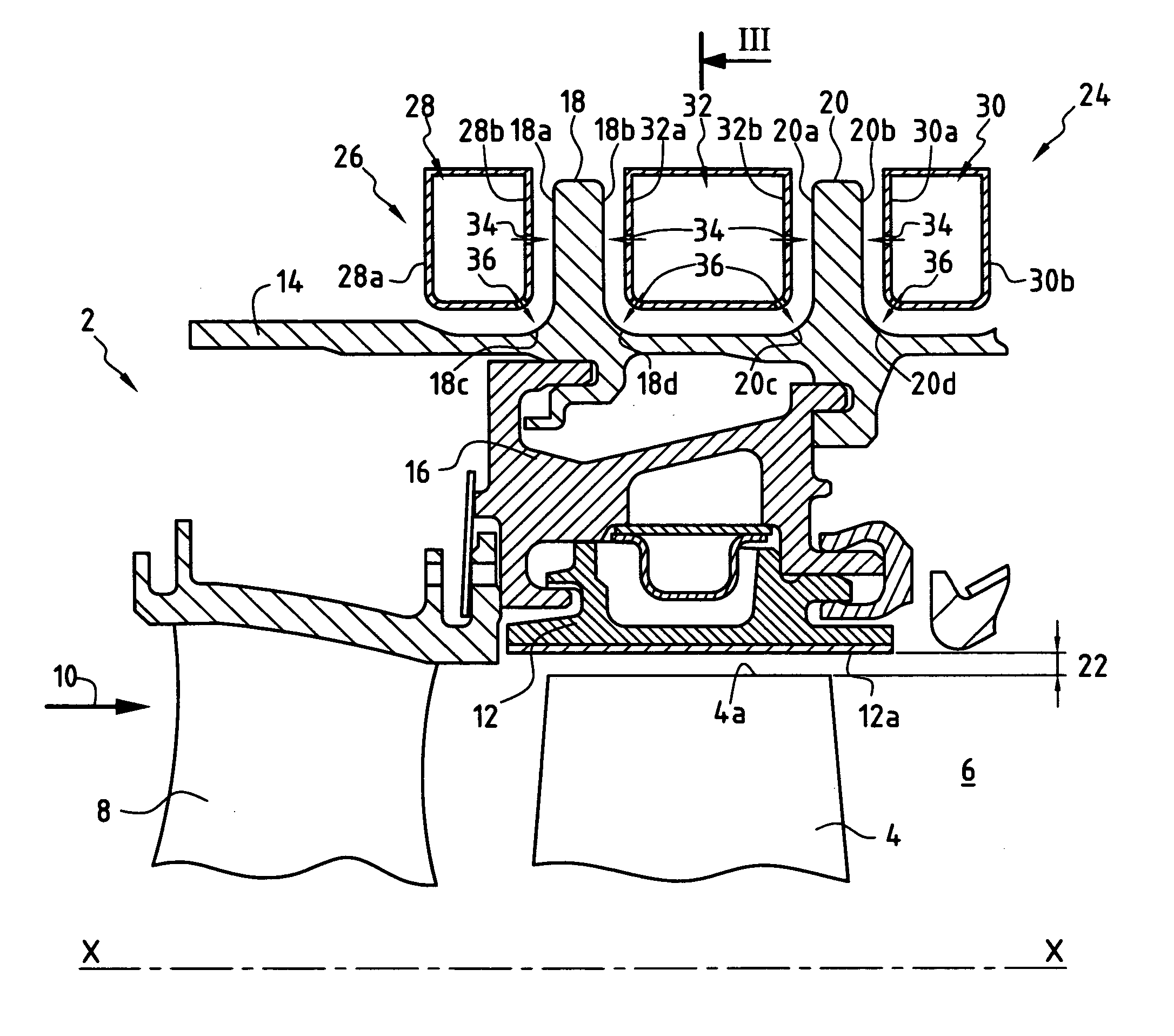
[0018]FIG. 1 is a longitudinal section which shows a high pressure turbine 2 of a turbomachine of longitudinal axis X-X. Nevertheless, the present invention could equally well be applied to a low-pressure turbine of a turbomachine or to any other gas turbine that is fitted with a device for controlling clearance at its blade tips.

[0019] The high-pressure turbine 2 consists, in particular, of a plurality of rotor blades 4 disposed in a stream 6 of hot gases that come from a combustion chamber (not shown) of the turbomachine. Said rotor blades 4 are disposed downstream from the stator blades 8 relative to the direction 10 in which the hot gases flow in the stream 6.

[0020] The rotor blades 4 of the high pressure turbine 2 are surrounded by a plurality of bushing segments 12 that are disposed circumferentially about the axis X-X of the turbine so as to form a circular and continuous surface. The bushing segments 12 are assembled via a plurality of spacers 16 on an annular casing 14, l...


PUM


Abstract

A clearance control device for controlling clearance between rotary blade tips and a stationary bushing of a gas turbine having a casing that is provided with at least two annular ridges, the clearance control device including a circular tuning unit that includes air circulation means for circulating air, said means being made up of at least three ducts; air supply means for supplying air to the air flow ducts; and air discharge means for discharging air on the ridges in order to modify the temperature, the air discharge means for each duct being made up of at least one top row having a number N of perforations disposed facing one of the side faces of the ridges and of at least one bottom row having a number 2N of perforations disposed facing a connection radius that connects the ridges to the casing.

Description

BACKGROUND OF THE INVENTION [0001] The present invention relates to the general field of controlling clearance between the tips of rotor blades and a stationary bushing in a gas turbine. [0002] By way of example, a gas turbine typically includes a plurality of stator blades disposed in alternation with a plurality of rotor blades in a passage for hot gases coming from a combustion chamber of the turbomachine. Over the entire circumference of the turbine, the rotor blades of the turbine are surrounded by a stationary bushing. Said stationary bushing defines a wall for the stream of hot gases passing through the turbine blades. [0003] In order to increase the efficiency of the turbine, it is known to reduce the clearance that exists between the tips of the rotor blades of the turbine and the portions of the stationary bushing that face said blades to as little as possible. [0004] To do this, means have been devised for varying the diameter of the stationary bushing. Generally, said me...

Claims


Application Information

Patent Timeline
Patent Type & Authority Applications(United States)
IPC IPC(8): F01D11/08F01D11/24F02C7/18F02C7/28
CPCF05D2230/13F01D11/24
Inventor AMIOT, DENISARRAITZ, ANNE-MARIEFACHAT, THIERRYGENDRAUD, ALAINLEFEBVRE, PASCALROUSSIN-MOYNIER, DELPHINE
Owner SN DETUDE & DE CONSTR DE MOTEURS DAVIATION S N E C M A
Why Eureka
Eureka Blog
Learn More