Graphics rendering and editing apparatus and method

a graphic object and editing technology, applied in static indicating devices, instruments, cathode-ray tube indicators, etc., can solve the problems of complicated relationship between curved portions and the position of curve control points, and achieve the effect of reducing user input operations for deforming graphic objects

Active Publication Date: 2016-01-12
CANON KK
View PDF13 Cites 0 Cited by
  • Summary
  • Abstract
  • Description
  • Claims
  • Application Information

AI Technical Summary

Benefits of technology

[0008]The present invention provides a graphics rendering and editing apparatus and method that reduces user input operations for deforming a graphic object.
[0010]In accordance with an aspect of the present invention, once a deformation attribute of a graphic object is specified, the graphic object can be deformed by only specifying a pre-change position and a post-change position of an arbitrary point by dragging or the like. User input operations for deforming a graphic object are reduced as a result.

Problems solved by technology

However, in the rendering program that renders a curve by adding curve-control points and setting weights for the curve-control points, the relationship between curved portions and the positions of curve-control points may be complicated.

Method used


Image

  • Graphics rendering and editing apparatus and method
  • Graphics rendering and editing apparatus and method
  • Graphics rendering and editing apparatus and method

Examples


Embodiment Construction

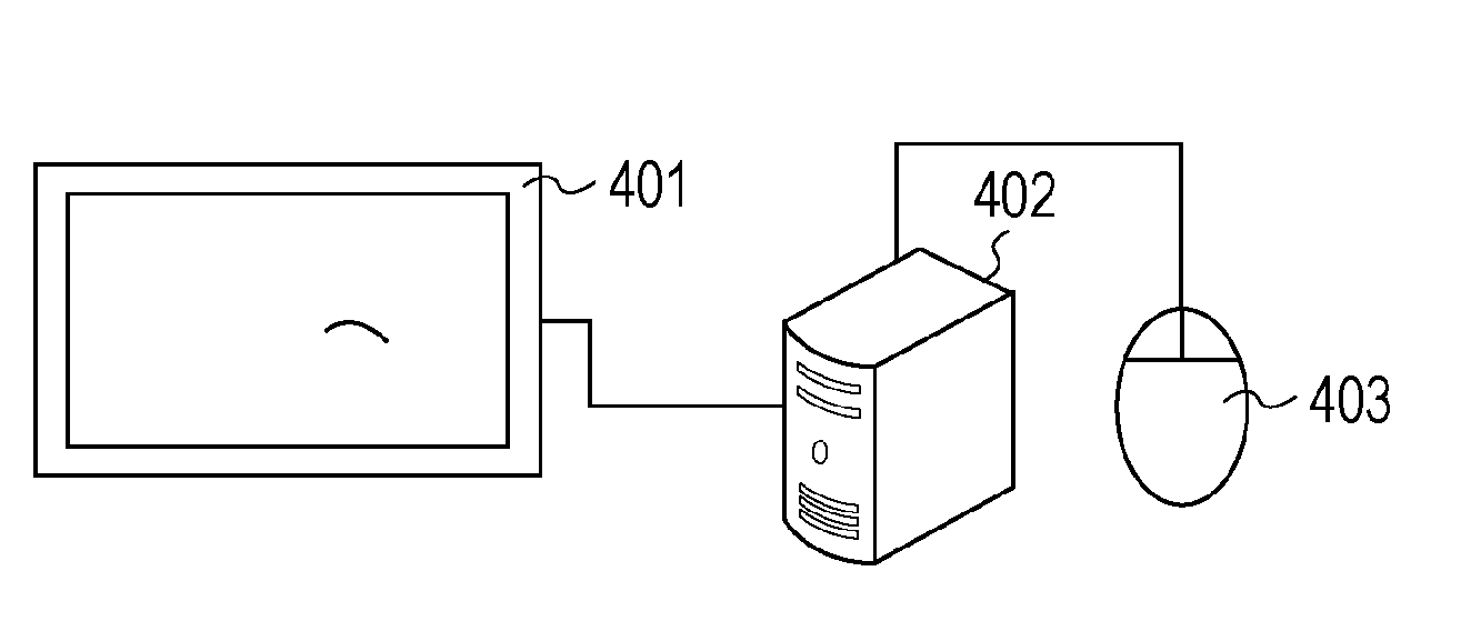
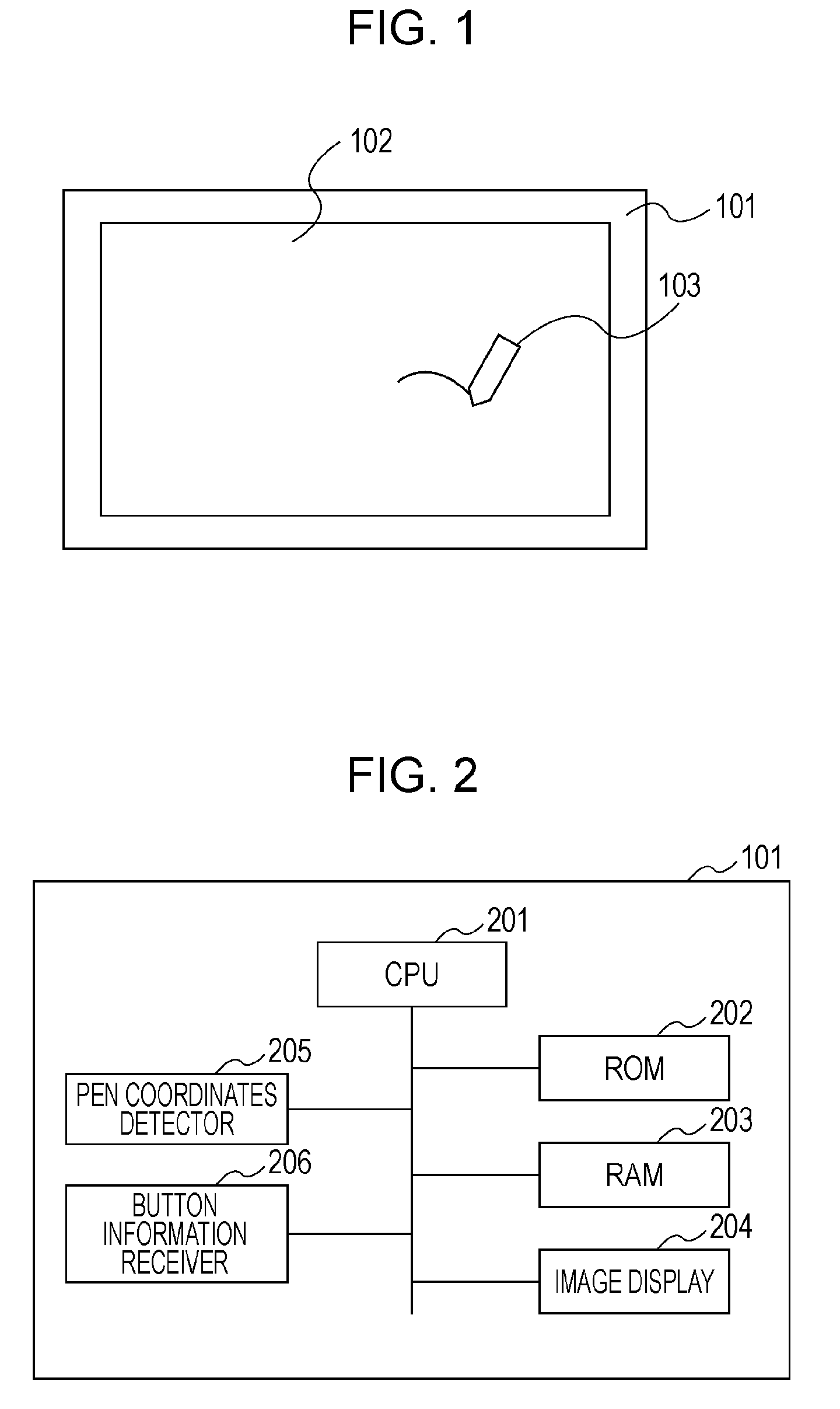
[0021]A display 101 is a device for implementing a graphics rendering and editing apparatus according to an exemplary embodiment of the invention. The display 101 includes a CPU 201, a ROM 202, a RAM 203, an image display 204, a pen coordinates detector 205, and a button information receiver 206.

[0022]The image display 204 has a display panel, and displays image data on a screen 102 in accordance with an instruction from the CPU 201. The pen coordinates detector 205 has a digitizer function, and detects the position of a pen 103 on the screen 102. The pen coordinates detector 205 detects the position of the pen 103 by monitoring how light is blocked when the screen 102 is irradiated with light from above. The positions of the pen 103 and its tip may also be electromagnetically or electrostatically detected. The button information receiver 206 receives button information of the pen 103 transmitted from the pen 103 with infrared rays. The term “button information” refers to informatio...


PUM


Abstract

A graphics rendering and editing apparatus includes a rendering unit configured to render a graphic object, a position specifying unit configured to specify a pre-change position and a post-change position of an arbitrary point on the graphic object, an attribute specifying unit configured to specify a deformation attribute of the graphic object, the deformation attribute being related to how the graphic object is deformed as a position of the arbitrary point changes, and a deformation unit configured to deform, when the position specifying unit has specified the pre-change position and the post-change position the graphic object in accordance with the pre-change position, the post-change position, and the attribute specified by the attribute specifying unit.

Description

BACKGROUND OF THE INVENTION[0001]1. Field of the Invention[0002]The present invention relates to a graphic rendering and editing apparatus and method for deforming graphic objects.[0003]2. Description of the Related Art[0004]A graphic rendering and editing apparatus may execute a rendering program that may dispose a graphic object, set up the graphic object, and edit the individual object. The rendering program may include a program that creates a curve by adding curve-control points of, for example, a Bezier curve, to a straight line and a curve. The rendering program renders a curve by first creating a line, then adding curve-control points, and then setting weights representing influences of the curve-control points.[0005]Japanese Patent Laid-Open No. 2002-63586 discloses an apparatus that creates a curve fitted to the shape of a graphic object, such as a circle or an ellipse. The apparatus creates the curve fitted to the graphic object by fixing one end of a straight line and dr...

Claims


Application Information

Patent Timeline
Patent Type & Authority Patents(United States)
IPC IPC(8): G09G5/00G06T11/60
CPCG06T11/60G09G5/00
Inventor IIJIMA, TADAHIKOSATO, NORIAKI
Owner CANON KK
Why Eureka
Try Eureka