Wide-angle photographic lens system enabling correction of distortion

a wide-angle, lens technology, applied in the field of wide-angle photographic lens system, can solve the problems of increasing production cost and increasing the price of the lens system, and achieve the effects of high resolution, small camera size, and high resolution

Active Publication Date: 2016-01-26
SEKONIX
View PDF0 Cites 1 Cited by
  • Summary
  • Abstract
  • Description
  • Claims
  • Application Information

AI Technical Summary

Benefits of technology

[0013]Accordingly, the present invention has been made keeping in mind the above problems occurring in the related art, and the present invention is intended to propose a wide-angle photographic lens system enabling correction of distortion, in which refractivities and shapes of respective lenses, incidence angles of a main beam of light in the lenses, and intervals between the lenses, etc. are appropriately designed, so the lens system can realize lightness and smallness and can enable correction of distortion, thereby providing wide-angle images having an angle of view of 90° or more.
[0019]As described above, the present invention provides a wide-angle photographic lens system composed of four lenses, which is used in a mobile phone camera, a digital camera, a PC camera, etc., realizes smallness of the camera, and provides wide-angle images having an angle of view of 90° or more and high resolution images.
[0020]Further, the wide-angle photographic lens system of this invention is configured such that, in a field not less than 60% of the maximum image height in the lens system, the incidence angle A_s of a main beam of light received on an iris is larger than the incidence angle A_fr of the main beam of light received on a tangent of the center of the front surface of the first lens, so a camera using the wide-angle photographic lens system can provide images having high resolution.

Problems solved by technology

As described above, although a plurality of techniques relating to optical lens systems have been proposed in the related art, a conventional wide-angle lens system having an angle of view of 90° or more is problematic in that the lens system excessively distorts images, and is not easy to realize smallness, and it increases production cost due to use of many lenses, thereby increasing the price of the lens system.

Method used


Image

  • Wide-angle photographic lens system enabling correction of distortion
  • Wide-angle photographic lens system enabling correction of distortion
  • Wide-angle photographic lens system enabling correction of distortion

Examples


first embodiment

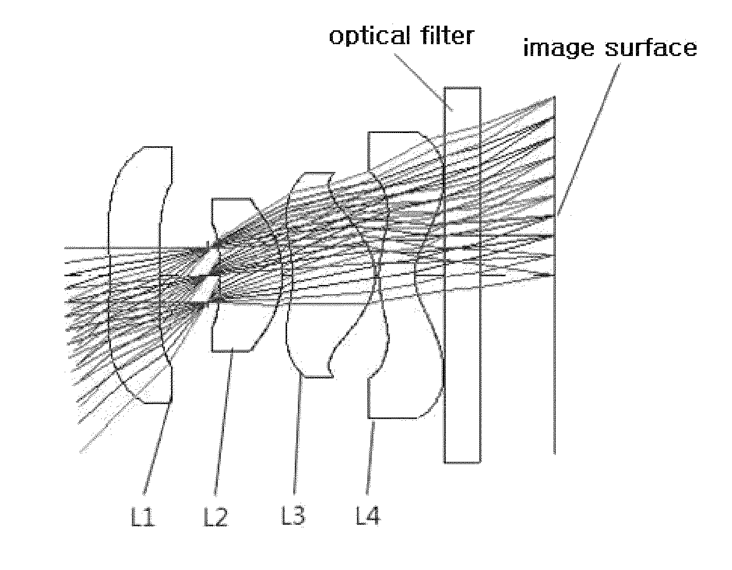
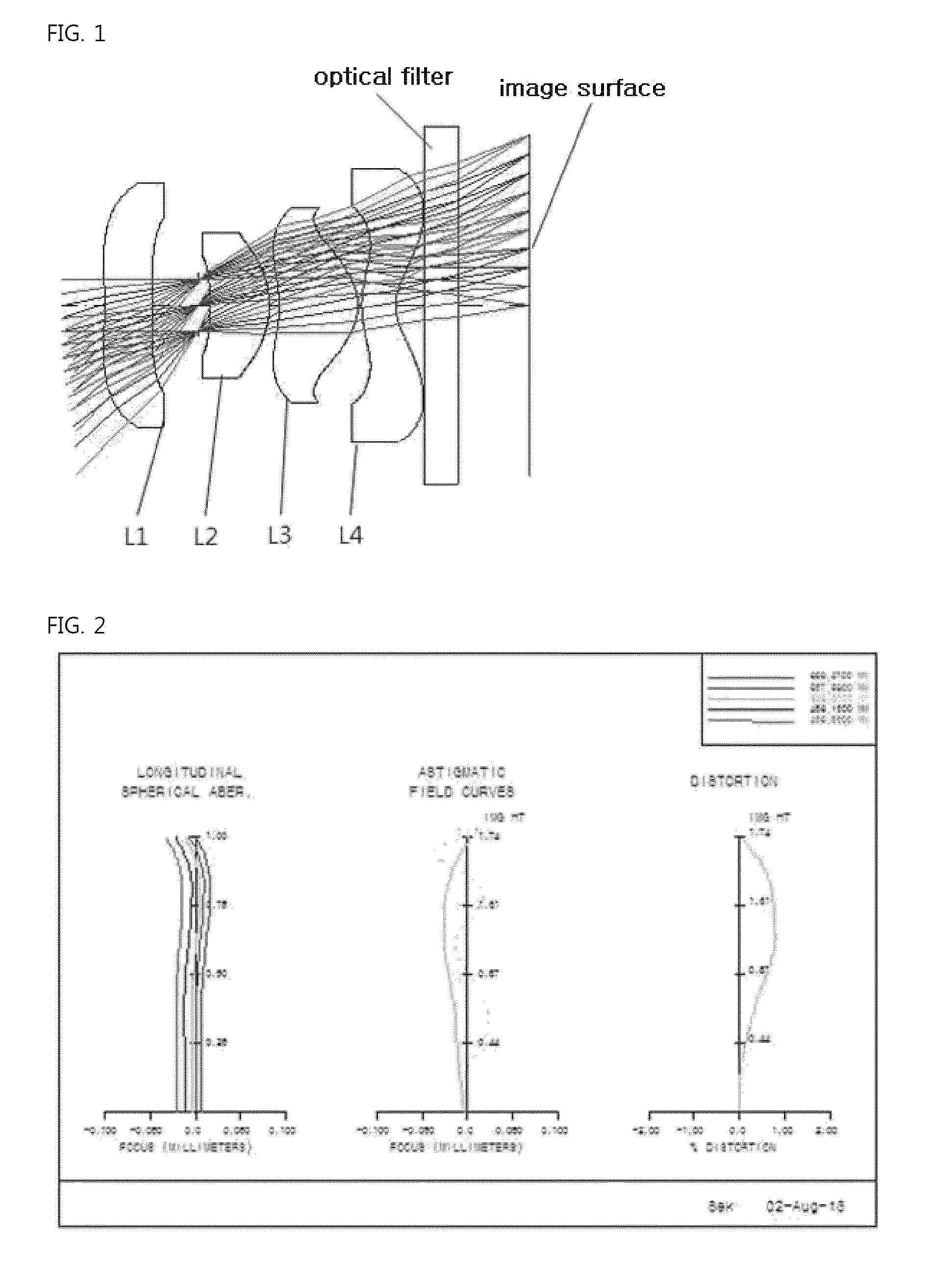
[0049]FIG. 1 shows a wide-angle photographic lens system having an angle of view of 100° according to a first embodiment of the present invention.

[0050]As shown in FIG. 1, in the first embodiment, a first lens L1, an iris, a second lens L2, a third lens L3 and a fourth lens L4 are sequentially arranged along an optical axis from an object.

[0051]Table 1 shows numerical data of respective lenses constituting the lens system according to the first embodiment of the present invention.

[0052]

TABLE 1Surface(surfaceRDY (radiusTHINdVdnumber)of curvature)(thickness)(refractivity)(ABBE number)OBJINFINITYINFINITY1−4.2320.421.53155.82−4.5230.39STOINFINITY0.114−3.8640.521.53155.85−0.9930.096−1.3810.691.53155.87−0.5940.0381.1580.301.637523.090.5590.2510INFINITY0.301.51764.211INFINITY0.62IMGINFINITY0.00(OBJ: object surface, STO: iris, IMG: image surface, Infinity: planar surface)

[0053]As shown in FIG. 1, the first lens L1, the iris STO, the second lens L2, the third lens L3 and the fourth lens L4 a...

second embodiment

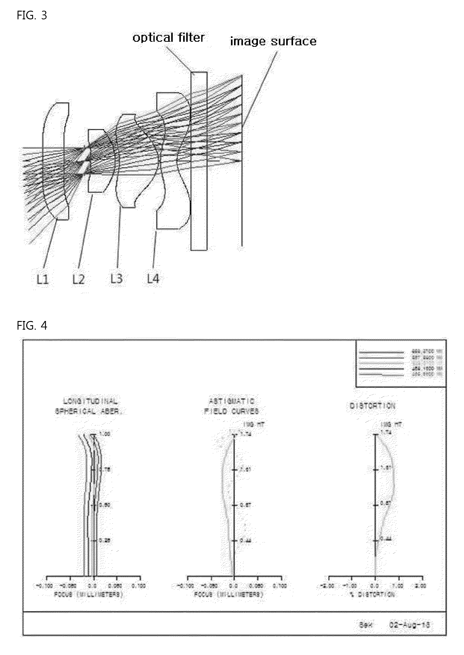
[0070]FIG. 3 shows a wide-angle photographic lens system having an angle of view of 100° according to a second embodiment of the present invention.

[0071]As shown in FIG. 3, a first lens L1, an iris, a second lens L2, a third lens L3 and a fourth lens L4 are sequentially arranged along an optical axis from an object.

[0072]Table 6 shows numerical data of respective lenses constituting the lens system according to the second embodiment of the present invention.

[0073]

TABLE 6SurfaceRDYVd(surface(radius ofTHINd(ABBEnumber)curvature)(thickness)(refractivity)number)OBJINFINITYINFINITY1−6.2270.381.53155.82−5.1320.38STOINFINITY0.114−2.7240.441.53155.85−0.9000.086−1.1710.711.53155.87−0.5770.0381.1320.301.637523.090.5660.2510INFINITY0.301.51764.211INFINITY0.62IMGINFINITY0(OBJ: object surface, STO: iris, IMG: image surface, Infinity: planar surface)

[0074]As shown in FIG. 3, the first lens L1, the iris STO, the second lens L2, the third lens L3 and the fourth lens L4 are sequentially arranged fro...

third embodiment

[0089]FIG. 5 shows a wide-angle photographic lens system having an angle of view of 100° according to a third embodiment of the present invention.

[0090]As shown in FIG. 5, a first lens L1, an iris, a second lens L2, a third lens L3 and a fourth lens L4 are sequentially arranged along an optical axis from an object.

[0091]Table 11 shows numerical data of respective lenses constituting the lens system according to the third embodiment of the present invention.

[0092]

TABLE 11SurfaceRDYVd(surface(radius ofTHINd(ABBEnumber)curvature)(thickness)(refractivity)number)OBJINFINITYINFINITY1−25.2240.571.53155.826.8170.31STOINFINITY0.0245.7700.431.53155.85−1.7510.056−1.8720.741.53155.87−0.5620.0481.0980.301.637523.090.5030.2110INFINITY0.301.51764.211INFINITY0.63IMGINFINITY0(OBJ: object surface, STO: iris, IMG: image surface, Infinity: planar surface)

[0093]As shown in FIG. 5, the first lens L1, the iris STO, the second lens L2, the third lens L3 and the fourth lens L4 are sequentially arranged from...


PUM


Abstract

A wide-angle photographic lens system enabling correction of distortion composed of four lenses, in which a first lens, an iris, a second lens, a third lens and a fourth lens sequentially arranged along an optical axis from an object, wherein the first lens has weak refractivity, the second lens has positive refractivity, the third lens has strong positive refractivity, and the fourth lens has negative refractivity, wherein the lens system satisfies relations, |f1 / f|>4, f3 / f<1.5, and te / tc<0.5, wherein f1 is a focal length of the first lens, f is a total focal length of all the lenses, f3 is a focal length of the third lens, to is a lens thickness on an effective diameter of a rear surface of the third lens, and tc is a center thickness of the third lens.

Description

CROSS REFERENCE TO RELATED APPLICATION(S)[0001]This application claims the benefit of Korean Patent Application No. 10-2013-0113178, filed on Sep. 24, 2013, entitled “Wide-angle photographic lens system enabling correction of distortion”, which is hereby incorporated by reference in its entirety into this application.BACKGROUND OF THE INVENTION[0002]1. Technical Field[0003]The present invention relates to a wide-angle photographic lens system composed of four lenses and, more particularly, to a wide-angle photographic lens system enabling correction of distortion, in which refractivities and shapes of respective lenses, incidence angles of a main beam of light in the lenses, and intervals between the lenses, etc. are appropriately designed, so the lens system can realize lightness and smallness and can enable correction of distortion, thereby having a distortion-corrected angle of view of 90° or more and providing an image with high resolution.[0004]2. Description of the Related Art...

Claims


Application Information

Patent Timeline
Patent Type & Authority Patents(United States)
IPC IPC(8): G02B9/58G02B15/14G02B13/04G02B13/00G02B3/02
CPCG02B9/58G02B13/004G02B13/04
Inventor CHOI, SOON CHULNAM, SEUNG NAMNOH, KI YOUN
Owner SEKONIX
Why Eureka
Try Eureka