Method and apparatus for extending the power output range of a power converter used for a lighting system

a technology of power converter and power output range, which is applied in the direction of lighting apparatus, electric lighting sources, and light sources. it can solve the problems of limited control range of le and te phase cut dimmers, and achieve the effect of reducing the operation time of the power converter

Inactive Publication Date: 2016-01-26
MICROCHIP TECH INC
View PDF23 Cites 0 Cited by
  • Summary
  • Abstract
  • Description
  • Claims
  • Application Information

AI Technical Summary

Benefits of technology

[0004]One objective of this patent is to disclose a simple method for controlling the power converter so that its output will be reduced to zero when the associated phase cut dimmer on the AC input exceeds a chosen delay value. This method uses an auxiliary timer to measure the times that the dimmer is both not providing and is providing power, proportionally reducing the power converter operation time when large phase cut values are in use. Another objective is to show how to add a controlled current sink to the system using an auxiliary timer so that the dimmer will be provided with minimum load current at all times. The sink current produces additional loading current which when added to or used to replace the power converter input current causes the dimmer to maintain normal operation as it would with an incandescent lamp. A third objective is to show how to produce an auxiliary current so that during certain times when the power converter is running but not drawing sufficient current, the total current drawn from the dimmer will keep the phase cut dimmer operating satisfactorily.

Problems solved by technology

One difficulty with this simple means of operation is that the majority of LE and TE phase cut dimmers have a limited control range.
As a result, when the dimmer is set to the maximum phase delay to give the minimum light output, there is still substantial AC power being converted to load power.

Method used


Image

  • Method and apparatus for extending the power output range of a power converter used for a lighting system
  • Method and apparatus for extending the power output range of a power converter used for a lighting system
  • Method and apparatus for extending the power output range of a power converter used for a lighting system

Examples


Embodiment Construction

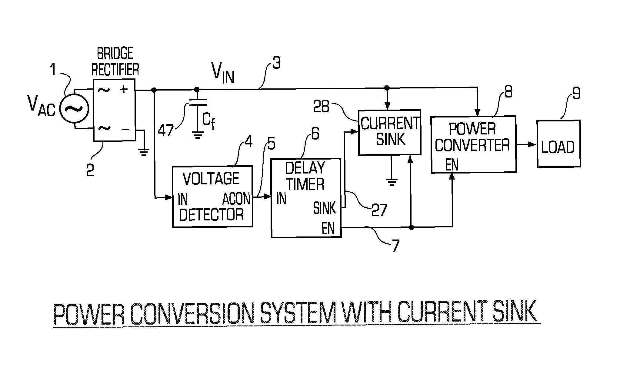
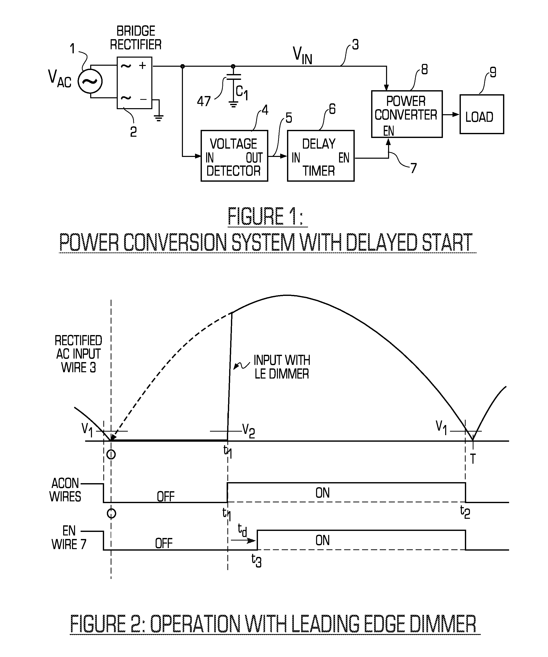
[0015]FIG. 1 shows a block diagram of a power conversion system with a delayed start time. In this system, the incoming AC line voltage Vac from source 1 is first converted to a full wave rectified voltage Vin on wire 3 by the bridge rectifier 2. Although the description here uses a full wave rectifier as known in the state of the art, a half wave rectifier or any other means of converting the incoming AC line voltage to a unipolar state could be used. The assumption here is that the power converter requires unipolar input voltage for proper operation. If that is not true, then the rectifier may be omitted or replaced with some other circuit.

[0016]The rectified input voltage Vin on wire 3 goes to a voltage detector 4, a power converter 8, and capacitor C1. Capacitor C1 denoted 47 is representative of capacitive filtering typically used to reduce electromagnetic interference (EMI) on the incoming power line. The EMI filter may be more complex than a simple capacitor as shown, but som...


PUM


Abstract

A method and system for extending the power output range of a power converter used for a lighting system is disclosed.

Description

FIELD[0001]A method and system for extending the power output range of a power converter used for a lighting system is disclosed.BACKGROUND[0002]A light emitting diode (LED) lighting system requires a power converter for changing the AC line voltage received from the utility power line to the DC power specific to the LED load circuit. A simple system for this purpose produces output current to the LED load whenever the incoming AC line voltage is sufficiently removed from zero. The power converter input current can be designed to represent a resistive load to the AC line input, giving a high power factor for the AC line input. In addition, the power converter input current may be sufficient to cause a phase cut lamp dimmer with either leading edge (LE) or trailing edge (TE) phase cut to operate correctly.[0003]One difficulty with this simple means of operation is that the majority of LE and TE phase cut dimmers have a limited control range. For example, if the AC half cycle is denot...

Claims


Application Information

Patent Timeline
Patent Type & Authority Patents(United States)
IPC IPC(8): H05B39/02H05B33/08H02M1/36H02M1/00H05B44/00
CPCH02M1/36H05B33/0815H02M2001/007H05B45/10H05B45/37H02M1/007
Inventor WALKER, JAMES, T.
Owner MICROCHIP TECH INC
Why Eureka
Try Eureka