Wire terminal structure

a wire terminal and wire terminal technology, applied in the direction of coupling device connection, coupling contact member, coupling base/case, etc., can solve the problems of poor reliability and durability of such wire terminals, very likely to break the press arm, and shorten the li

Active Publication Date: 2016-02-16
SWITCHLAB SHANGHAI +1
View PDF5 Cites 10 Cited by
  • Summary
  • Abstract
  • Description
  • Claims
  • Application Information

AI Technical Summary

Benefits of technology

[0009]It is therefore a primary object of the present invention to provide an improved wire terminal structure to overcome the shortcomings of the conventional wire terminal, which is capable of fully enclosing internal components to prevent external dust or impurity from entering the insulation case to affect the normal operation thereof.

Problems solved by technology

The insulation case is generally made of plastic material so that the press arm is very likely to break.
Therefore, the reliability and durability of such wire terminal are poor.
As a result, the external dust, impurity and moisture are very likely to go through the gap into the insulation case to affect the normal operation of the wire terminal and shorten the lifetime thereof.

Method used


Image

  • Wire terminal structure
  • Wire terminal structure
  • Wire terminal structure

Examples


Embodiment Construction

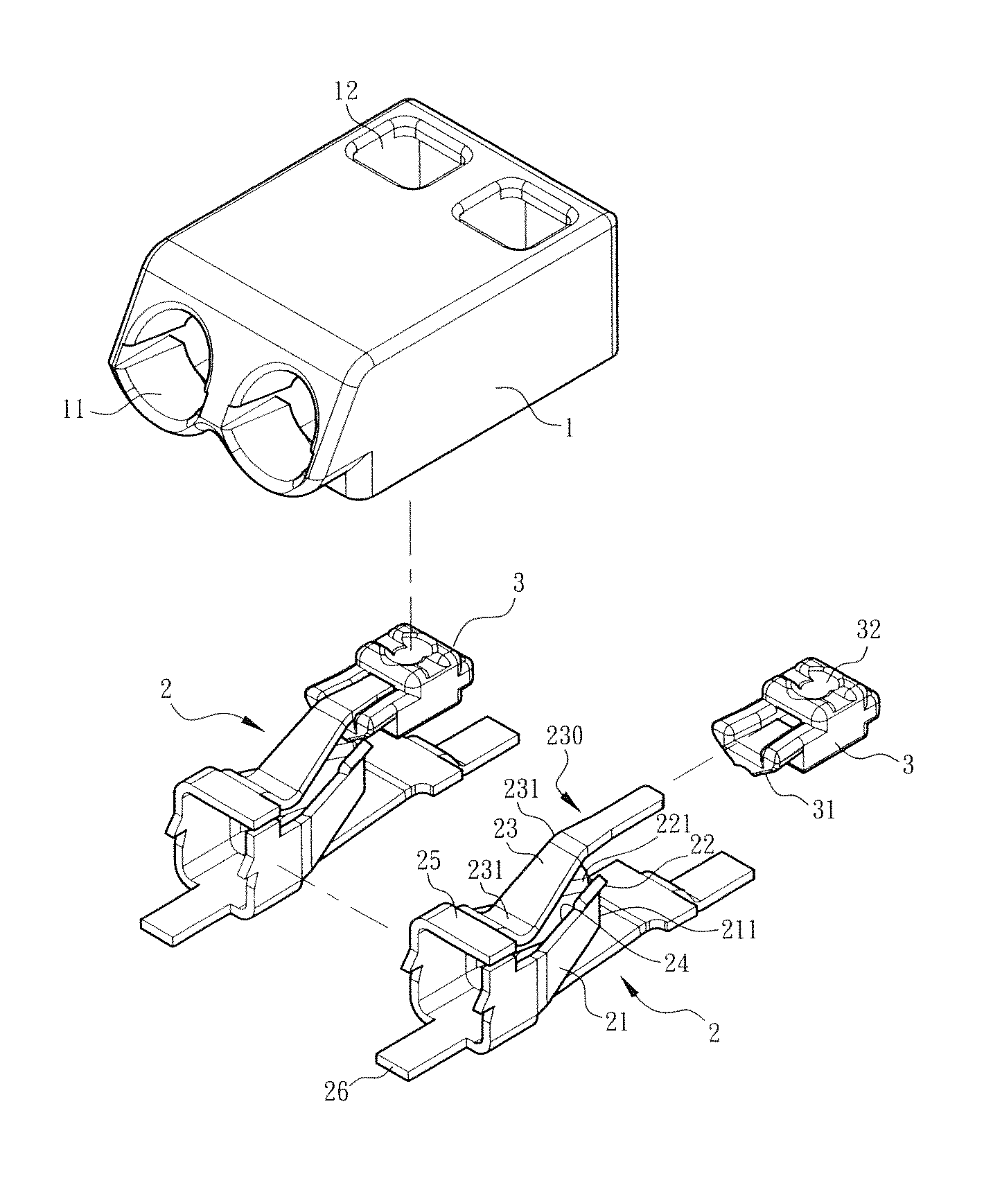
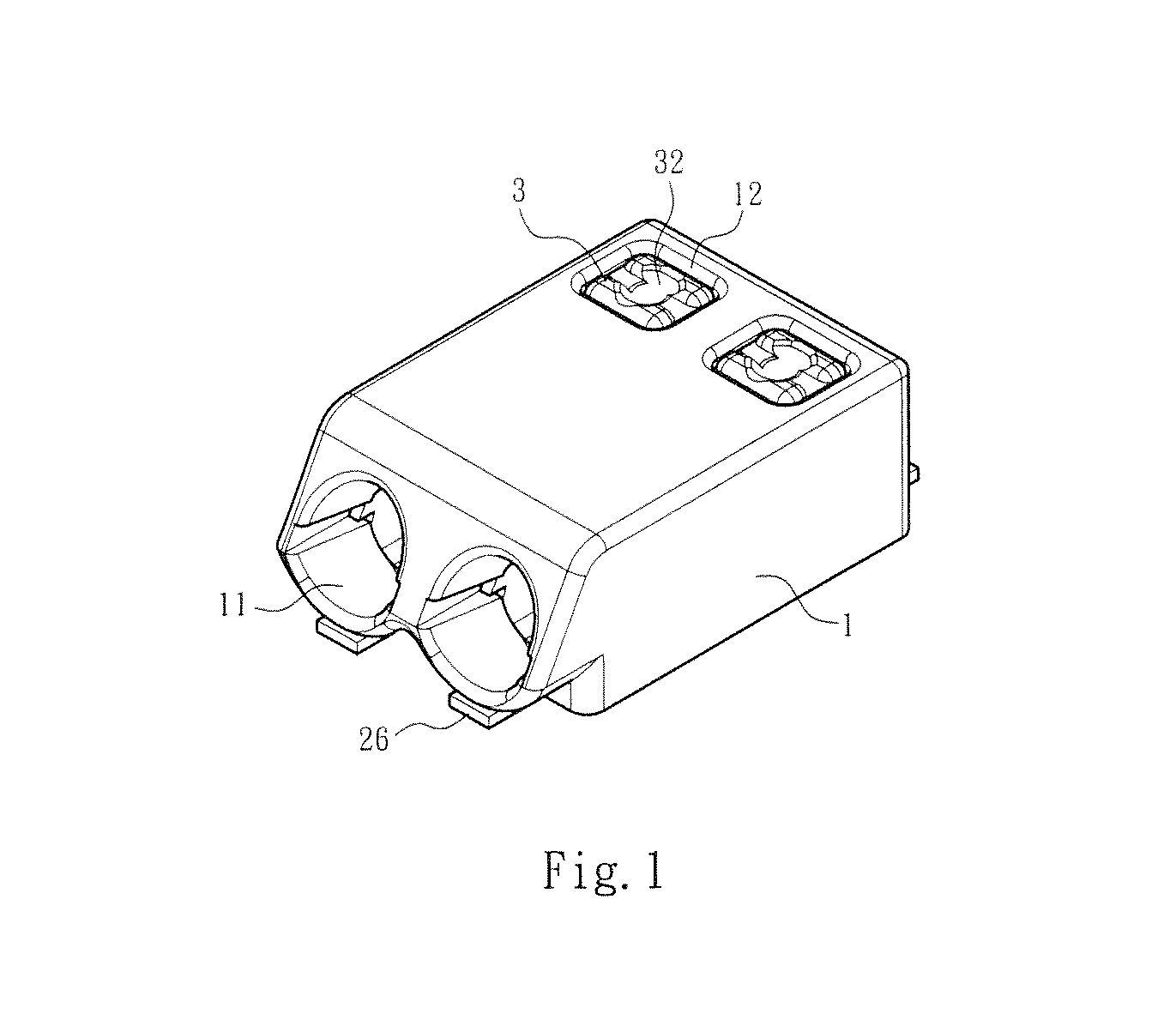
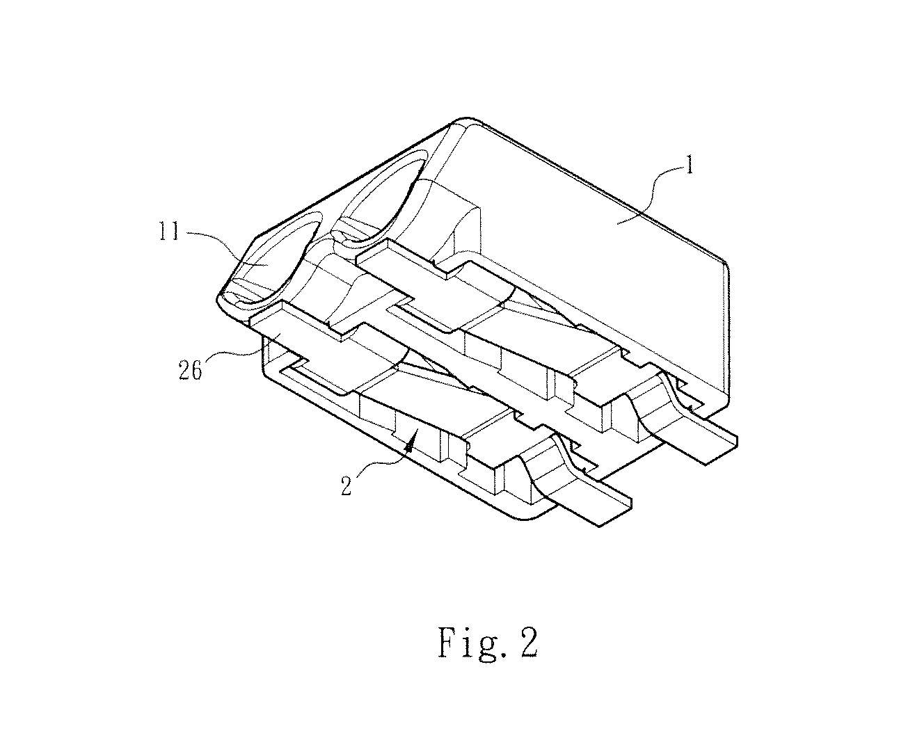
[0034]Please refer to FIGS. 1 to 8. FIG. 1 is a perspective assembled view of a preferred embodiment of the present invention. FIG. 2 is a bottom perspective view of the preferred embodiment of the present invention according to FIG. 1. FIG. 3 is a perspective exploded view of the preferred embodiment of the present invention according to FIG. 1. FIG. 4 is a perspective exploded view according to FIG. 3, seen from another angle. FIG. 5 is a side sectional view of the preferred embodiment of the present invention according to FIG. 1.

[0035]FIG. 6 is a sectional view taken along line A-A of FIG. 5. FIG. 7 is a sectional view according to FIG. 5, showing the use of the present invention. FIG. 8 is a sectional view according to FIG. 6, showing the use of the present invention.

[0036]As shown in the drawings, the wire terminal structure of the present invention includes an insulation case 1 and a conductive holding frame 2 disposed in the case 1. One end of the case 1 is formed with a wire...


PUM


Abstract

A wire terminal structure capable of fully enclosing internal components to prevent external dust or impurity from entering the insulation case to affect the normal operation thereof. The wire terminal structure includes an insulation case and a conductive holding frame disposed in the case. The case is formed with a wire socket and a press window. The conductive holding frame has an elastic holding member corresponding to the wire socket. The elastic holding member is formed with a holding mouth. A push section is disposed on the elastic holding member corresponding to the press window. A pushbutton is elastically movably disposed in the press window between the press window and the push section. The pushbutton is spaced from the case. When an external force is applied to the pushbutton, the pushbutton is elastically moved to push the push section and open the holding mouth.

Description

BACKGROUND OF THE INVENTION[0001]1. Field of the Invention[0002]The present invention relates generally to an improved wire terminal structure, and more particularly to a wire terminal structure for the wire connected to an electronic component such as an LED. The wire terminal structure is capable of fully enclosing internal components to prevent external dust or impurity from entering the insulation case to affect the normal operation thereof.[0003]2. Description of the Related Art[0004]A wire terminal or so-called connector is used to connect the metal conductive wires (electrical wires) between electronic components or connect the conductive wires between electronic components and circuit board. The electronic components can be a resistor, a capacitor, an inductor, an LED, a transformer, a liquid crystal panel, a touch panel or the like. The wire terminal serves to transmit power or electronic signal to facilitate the installation and layout of the internal circuit board and ele...

Claims


Application Information

Patent Timeline
Patent Type & Authority Patents(United States)
IPC IPC(8): H01R13/193H01R13/52H01R4/48H01R13/24H01R13/629
CPCH01R13/52H01R4/4827H01R4/4836H01R13/2407H01R13/629H01R12/515H01R4/48365H01R4/48275
Inventor WU, CHIH-YUANCHEN, WEI-CHILIU, SHIH-CHUNGCHANG, SHAO-TE
Owner SWITCHLAB SHANGHAI
Why Eureka
Try Eureka