Supercharge Your Innovation With Domain-Expert AI Agents!

Sample holder and method for observing electron microscopic image

a technology sample holder, which is applied in the field of electron microscopic image observation techniques, can solve the problems of difficult to acquire high contrast images, and achieve the effects of reducing image contrast, improving resolution, and charging

Active Publication Date: 2016-02-23
NAT INST OF ADVANCED IND SCI & TECH
View PDF13 Cites 2 Cited by
  • Summary
  • Abstract
  • Description
  • Claims
  • Application Information

AI Technical Summary

Benefits of technology

The solution significantly reduces electron beam damage and improves image resolution and contrast, allowing for high-resolution, high-contrast observations of biological samples at atmospheric pressure without staining, enabling the observation of inner structures and living samples.

Problems solved by technology

Unfortunately, there are problems in that such a biological sample is susceptible to damage due to electron beam irradiation and it is difficult to acquire a high contrast image.

Method used


Image

  • Sample holder and method for observing electron microscopic image
  • Sample holder and method for observing electron microscopic image
  • Sample holder and method for observing electron microscopic image

Examples


Embodiment Construction

[0052]Hereinafter, referring to the drawings, a sample holder and a method of observing an electron microscopic image using the same are described.

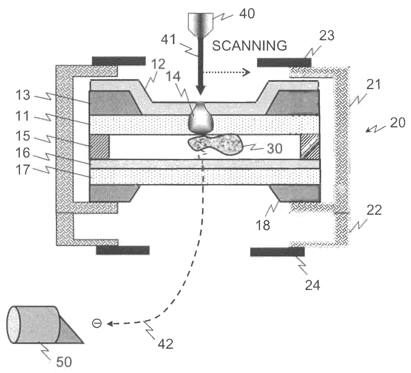
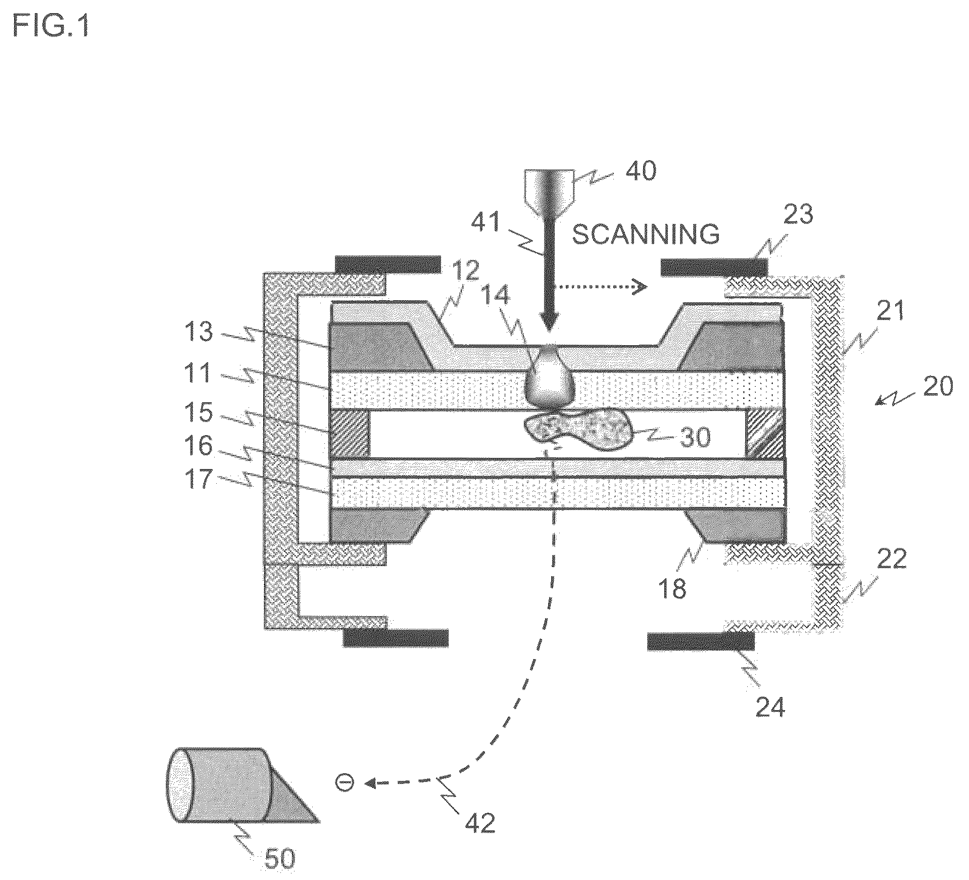
[0053]FIG. 1 is a block diagram for illustrating an overview of a configuration example of a sample holder according to the present invention. In the example shown in this diagram, the sample holder 20 includes an upper main body 21 and a lower main body 22. In the upper main body 21, a laminate of an insulative thin film 11 and a secondary electron emission protective thin film 12 is provided. An electron beam 41 emitted from an electron gun 40 enters the secondary electron emission protective thin film side. The undersurface of the insulative thin film 11 is a sample adhesion surface, where a sample 30 to be an observation target is held by adsorption or the like. What is indicated by signs 13 and 18 are frames for securing the mechanical strength of the sample holder 20.

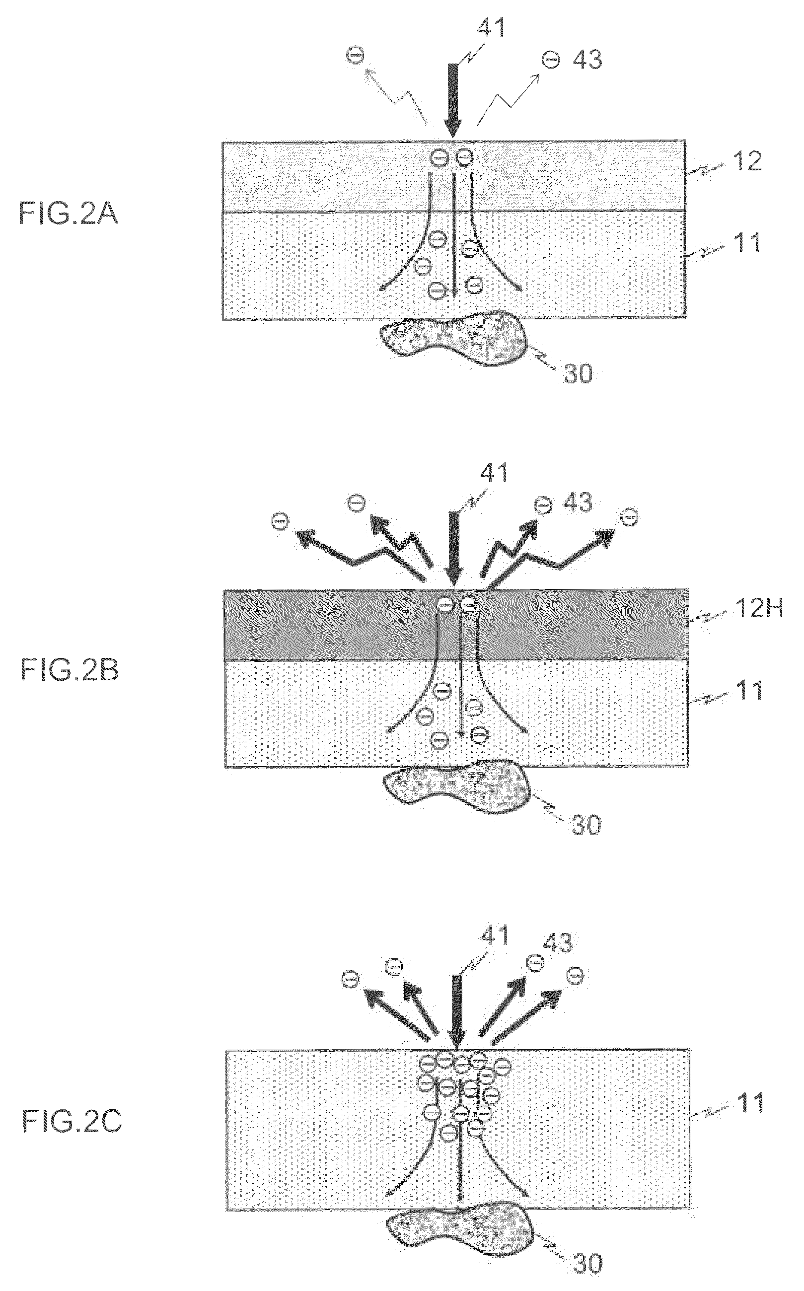
[0054]The secondary electron emission protective thin film 12 is m...


PUM

PropertyMeasurementUnit
thicknessaaaaaaaaaa
thicknessaaaaaaaaaa
diameteraaaaaaaaaa

Abstract

In an upper main body of a sample holder, a laminate of an insulative thin film and a secondary electron emission protective thin film is provided. An electron beam emitted from an electron gun enters the secondary electron emission protective thin film side. The undersurface of the insulative thin film is a sample adhesion surface, where a sample to be an observation target is held by adsorption or the like. The secondary electron emission protective thin film is made of a material having a low secondary electron emission coefficient δ and, preferably, is non-insulative. That is, the secondary electron emission protective thin film is conductive even though the electric resistance is high. Accordingly, the charge level of a site irradiated with the electron beam has a low charge level.

Description

TECHNICAL FIELD[0001]The present invention relates to a technique for observing an electron microscopic image and, in particular, to a technique suitable for observing an organic material sample and a biological sample that are susceptible to damage due to electron beam irradiation as an electron microscope image that is sharp and has high contrast.BACKGROUND ART[0002]A scanning electron microscope (SEM) has been widely used not only for morphological observation on an inorganic material sample or an organic material sample but also for observation on a biological sample, and is an apparatus suitable for observing microorganisms, such as bacteria and viruses, which cannot be observed by the unaided eye.[0003]Unfortunately, there are problems in that such a biological sample is susceptible to damage due to electron beam irradiation and it is difficult to acquire a high contrast image. For SEM observation on a biological sample, typically, a sample as an observation target is pretreat...

Claims


Application Information

Patent Timeline
Patent Type & Authority Patents(United States)
IPC IPC(8): H01J37/26H01J37/20G01N23/225H01J37/28
CPCH01J37/261G01N23/225H01J37/20H01J2237/004H01J2237/2003
Inventor OGURA, TOSHIHIKO
Owner NAT INST OF ADVANCED IND SCI & TECH
Features
  • R&D
  • Intellectual Property
  • Life Sciences
  • Materials
  • Tech Scout
  • Unparalleled Data Quality
  • Higher Quality Content
  • 60% Fewer Hallucinations
Learn More