A rechargeable drone

An unmanned aerial vehicle and rechargeable technology, applied in the field of rechargeable unmanned aerial vehicles, can solve the problems of complex structure of charging piles, and achieve the effects of low manufacturing cost, easy portability and simple structure design.

Active Publication Date: 2021-06-11
张若晗
View PDF14 Cites 0 Cited by
  • Summary
  • Abstract
  • Description
  • Claims
  • Application Information

AI Technical Summary

Problems solved by technology

[0008] The purpose of the present invention is to overcome the problem of the complex structure of the unmanned aerial vehicle charging pile in the prior art, and to provide a rechargeable unmanned aerial vehicle; The charging interface matched with the charging socket, so as to charge the drone; in addition, the charging process is controlled by the gravity of the drone itself. When the drone lands on the charging pile, the telescopic guide rod is forced to shorten. The connecting rod drives the slider to move and touches the touch switch to realize charging; the whole charging pile has a simple structure design and low manufacturing cost

Method used


Image

  • A rechargeable drone
  • A rechargeable drone
  • A rechargeable drone

Examples


Embodiment 1

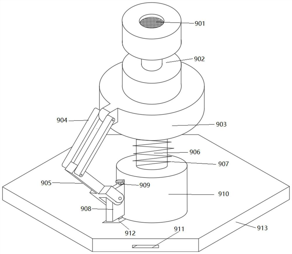
[0045] A rechargeable unmanned aerial vehicle in this embodiment includes an unmanned aerial vehicle and a charging pile, wherein the charging pile is such as figure 1 As shown, the charging pile includes a base 910 arranged on a chassis 913, and a telescopic guide rod 906 is vertically installed on the base 910. The telescopic guide rod 906 of this embodiment is vertically arranged on the upper surface of the base 910, and the telescopic The guide rod 906 can expand and contract along its length. A disc 903 is provided on the top of the telescopic guide rod 906, and a charging interface 901 is provided on the upper surface of the disc 903. A charging socket 900 used in conjunction with a charging interface 901 is provided on the surface.

[0046] In addition, in this embodiment, a return spring 907 is sheathed outside the telescopic guide rod 906; figure 1 As shown, in this embodiment, a connecting rod is provided on the side wall of the disk 903, and the connecting rod is ...

Embodiment 2

[0052] A rechargeable drone of this embodiment is basically the same as that of Embodiment 1, except that the slider 908 causes damage to the touch switch 912 in order to prevent the drone itself from being too heavy. ,Such as figure 1 As shown, the connecting rod in this embodiment includes a buffer rod 904 and a booster rod 905. One end of the buffer rod 904 is hinged to the side wall of the disc 903, and the other end of the buffer rod 904 is hinged to the booster rod 905. The booster The rod 905 is hinged to the slider 908 .

[0053] Due to the existence of the buffer rod 904 and the booster rod 905, when the drone exerts force on the charging pile, the buffer rod 904 and the booster rod 905 will rotate, making the slider 908 move slower on the chute 909, thereby The impact of the slider 908 on the touch switch 912 is effectively avoided.

[0054] In addition, in this embodiment, a charging port 911 is provided on the side of the chassis 913, and the charging port 911 ca...

Embodiment 3

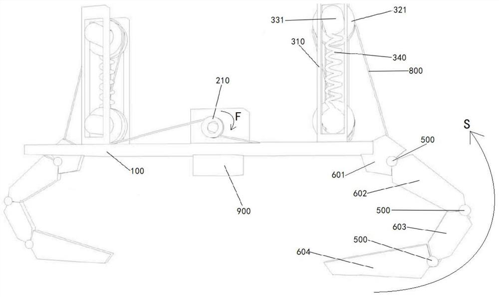
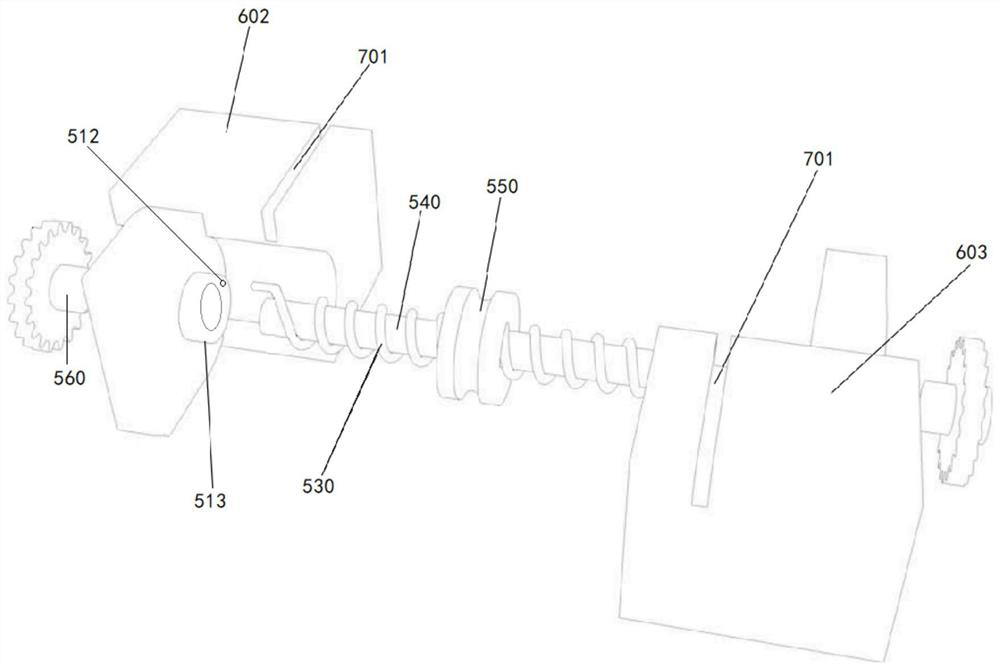
[0057] A rechargeable unmanned aerial vehicle of the present embodiment is basically the same as that of the second embodiment, except that the base plate 100 of the unmanned aerial vehicle of the present embodiment is as follows: figure 1 As shown, fixed arms 601 are provided on both side edges of the UAV bottom plate 100, and the number of fixed arms 601 is at least two, which can be two, four, six... Preferably, the There are two fixed arms 601 , and the two fixed arms 601 are arranged symmetrically with respect to the central axis of the UAV bottom plate 100 . One end of the fixed arm 601 is fixedly mounted on the base plate 100 of the drone, the other end of the fixed arm 601 is rotationally connected with the upper end of the first mechanical arm 602 through the rotating assembly 500, and the lower end of the first mechanical arm 602 is connected through a rotating assembly 500 It is rotatably connected with the upper end of the second mechanical arm 603 , and the lower ...


PUM


Abstract

The invention discloses a rechargeable unmanned aerial vehicle, which belongs to the technical field of unmanned aerial vehicle charging. The present invention includes an unmanned aerial vehicle and a charging pile. The charging pile includes a base arranged on the chassis. A telescopic guide rod is vertically installed on the base. The top end of the telescopic guide rod is connected with a disc. A return spring is sheathed on the outside; a charging interface is provided on the upper surface of the disc; a connecting rod is provided on the side wall of the disc, and the connecting rod is connected with a slider, and the slider is slidably installed on the chute , and the chute is set on the side wall of the base, the chassis is provided with a touch switch, the touch switch is located directly below the slider; The charging socket used. The present invention charges the drone by providing a charging interface on the charging pile that matches the charging socket on the drone; the entire charging pile has a simple structure design and low manufacturing cost.

Description

technical field [0001] The invention relates to the technical field of unmanned aerial vehicle charging, and more specifically, relates to a rechargeable unmanned aerial vehicle. Background technique [0002] With the development of science and technology, the application fields of drones are becoming more and more extensive. Compared with manned aircraft, drones are often more suitable for tasks that are too "dumb, dirty or dangerous". At present, it is widely used in aerial photography, agriculture, plant protection, micro selfie, express delivery, disaster relief, observation of wild animals, monitoring of infectious diseases, surveying and mapping, news reports, power inspection, disaster relief, film and television shooting, and romance creation. The use of the drone itself. [0003] During the operation of the existing unmanned aerial vehicle, due to the limitation of its volume, the capacity of the battery carried is limited, so that the unmanned aerial vehicle canno...

Claims


Application Information

Patent Timeline
Patent Type & Authority Patents(China)
IPC IPC(8): B60L53/31B60L53/16B60L53/35B64F1/00
CPCB64F1/00B60L53/16B60L53/31B60L53/35Y02T10/70Y02T10/7072Y02T90/12Y02T90/14
Inventor 张若晗夏国富
Owner 张若晗
Why Eureka
Try Eureka