
Multifunctional submerging and floating device with unmanned aerial vehicle taking-off and landing platform

A technology for take-off and landing platforms and drones, which is applied to circuit devices, battery circuit devices, motor vehicles, etc., can solve the problems of difficult charging, unmanned aerial vehicles cannot be docked and charged, and achieves high safety in use and extended battery life. , the effect of prolonging the use time

Pending Publication Date: 2018-02-09
余拓
View PDF9 Cites 17 Cited by
  • Summary
  • Abstract
  • Description
  • Claims
  • Application Information

AI Technical Summary

Problems solved by technology

[0006] In order to solve the problem that the existing unmanned aerial vehicle cannot be docked and charged on the sea surface, and the electronic equipment for detection or monitoring on the seabed is difficult to charge, the present invention provides an unmanned aerial vehicle that can take off and land, float and charge, and can A multi-functional diving and floating device that dives to the bottom of the sea to charge electronic equipment on the bottom of the sea

Method used


Image

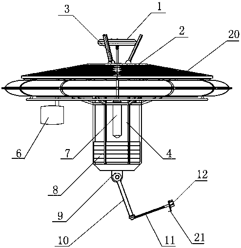
  • Multifunctional submerging and floating device with unmanned aerial vehicle taking-off and landing platform
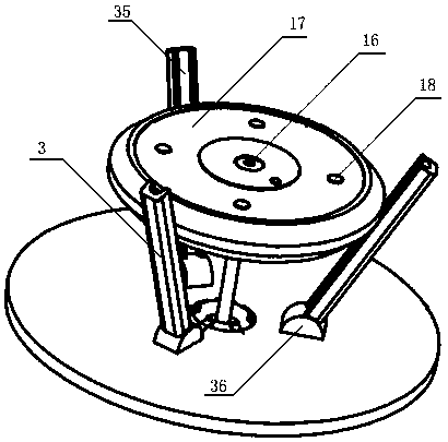
  • Multifunctional submerging and floating device with unmanned aerial vehicle taking-off and landing platform
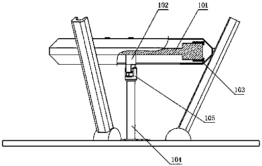
  • Multifunctional submerging and floating device with unmanned aerial vehicle taking-off and landing platform

Examples


Embodiment 2

[0086] Such as Figure 14 , Figure 15 As shown, on the basis of Embodiment 1 or 2, the power drive device 6 of the present embodiment includes a wind deflector 61, a speed regulating motor 62, a propeller 63, a steering motor 64 and a rudder stock 65; The output shaft of the motor 64 is fixedly connected, and the other end is fixedly connected with the speed-regulating motor 62; the output shaft of the speed-regulating motor 62 is fixedly connected with the paddle shaft of the propeller 63; And it is fixedly connected with the speed regulating motor 62 .

[0087] When the floating cabin is floating on the sea surface, it needs to cooperate with the take-off and landing of the drone. At this time, the floating cabin needs to move to cooperate with the take-off and landing of the drone. The speed-regulating motor 62 drives the propeller 63 to make the floating cabin move on the sea surface. The control or controller adjusts the rotational speed of the speed-regulating motor 6...

Embodiment 3

[0092] On the basis of embodiment 2, the high-pressure submersible pump 7 of the present embodiment is a high-pressure submersible pump, such as Figure 16 Shown, comprise pump body 71, be arranged on the 3rd air bag 72 of pump body 71 bottoms and rubber protective cover 73, rubber protective cover 73 cover is arranged on the outside of the 3rd air bag 72; Rubber protective cover plays a protective role to air bag, can The service life of the air bag is extended, and the rubber protective cover also improves the high pressure resistance of the entire pump body.

[0093] In order to increase the high pressure resistance of the airbag itself, the third airbag 72 of this embodiment includes a first capsule 74 and a second capsule 75, the first capsule 74 is a cylinder, the second capsule 75 is a hemisphere, and the first capsule 75 is a hemisphere. The capsule body 74 and the second capsule body 75 are integrally formed; the first capsule body 74 is embedded in the bottom end of ...

Embodiment 4

[0097] On the basis of Embodiment 1, in order to further realize the function of the floating cabin, first airbags 197 are provided in the compartments of the floating cabin in this embodiment, and the first airbags 197 are pre-filled with gas of a certain pressure to ensure that Under the condition of a certain depth, the airbag can still push seawater out of the floating chamber through its own air pressure. In this embodiment, the first airbags 197 are prefilled with gas at two atmospheric pressures, and each first airbag 197 is provided with an air outlet and an air inlet. When an airbag is accidentally damaged, the floating cabin can be used normally, which improves the safety of use.

[0098] Baffles are arranged in each subdivision body, and the baffles are arranged along the longitudinal section of the subdivision body to separate the first airbag 197 from the injected water, and the baffles move back and forth along the inner wall of the subdivision body under the act...


PUM


Abstract

The invention discloses a multifunctional submerging and floating device with an unmanned aerial vehicle taking-off and landing platform. The multifunctional submerging and floating device comprises afloating cabin, the unmanned aerial vehicle taking-off and landing platform, a high-pressure submersible pump, a balance weight cabin and a power drive device. Solar cell panels are arranged, so thatsolar energy serves as an energy source. The multifunctional submerging and floating device is provided with an energy storage device, and an unmanned aerial vehicle, all types of instruments and equipment carried on the multifunctional submerging and floating device and submarine electronic equipment can be charged. Through the maneuverability of the power drive device, the position of the multifunctional submerging and floating device can be adjusted or the multifunctional submerging and floating device can slowly move to the designated position. The multifunctional submerging and floatingdevice is simple in structure, flexible in loading and transporting and quick to arrange; and on the base of the platform, the functions of exploration, receiving, storage, launching, object transit shipment and the like can be expanded as well, and the device is extended to be the universal type multifunctional submerging and floating device which can process all types of information and integrate multiple functions.

Description

technical field [0001] The invention belongs to the technical field of diving and floating devices, and in particular relates to a multifunctional diving and floating device which can be used for take-off and landing, floating and charging of unmanned aerial vehicles, and can dive to the seabed to charge electronic equipment on the seabed. Background technique [0002] At present, my country's naval forces use a large number of drones for reconnaissance, search and rescue tasks, and drones cannot be docked and charged on the sea surface; in addition, electronic equipment for detection or monitoring on the seabed also has the problem of charging difficulties, which has caused great problems in its use. limitations. [0003] The patent with the application number "201621169205.3" discloses a UAV floating cabin for distributed sampling of the wetland water surface environment, including a floating cabin and a multi-rotor drone matched with it. The shape of the floating cabin is ...

Claims


Application Information

Patent Timeline
Patent Type & Authority Applications(China)
IPC IPC(8): B63B35/00B63B11/00B63H1/14B63G8/22B64D45/06H02J7/35
CPCH02J7/35B63B11/00B63B35/00B63G8/22B63H1/14B64D45/06Y02T10/70
Inventor 余拓
Owner 余拓
Learn More