Storage battery charge and discharge circuit topology

A charging and discharging circuit and storage battery technology, applied in the electrical field, can solve the problems of unable to discharge the power grid, and achieve the effects of small harmonic pollution, wide output voltage range, and high charging and discharging efficiency

Active Publication Date: 2012-10-24
XIAN ACTIONPOWER ELECTRIC
View PDF2 Cites 15 Cited by
  • Summary
  • Abstract
  • Description
  • Claims
  • Application Information

AI Technical Summary

Problems solved by technology

[0003] Taking the resonant converter topology mentioned in this article as an example, as Figure 4 As shown, the H-bridge soft switching is

Method used


Image

  • Storage battery charge and discharge circuit topology
  • Storage battery charge and discharge circuit topology
  • Storage battery charge and discharge circuit topology

Examples


Example Embodiment

[0027] The present invention will be described in detail below in conjunction with the drawings.

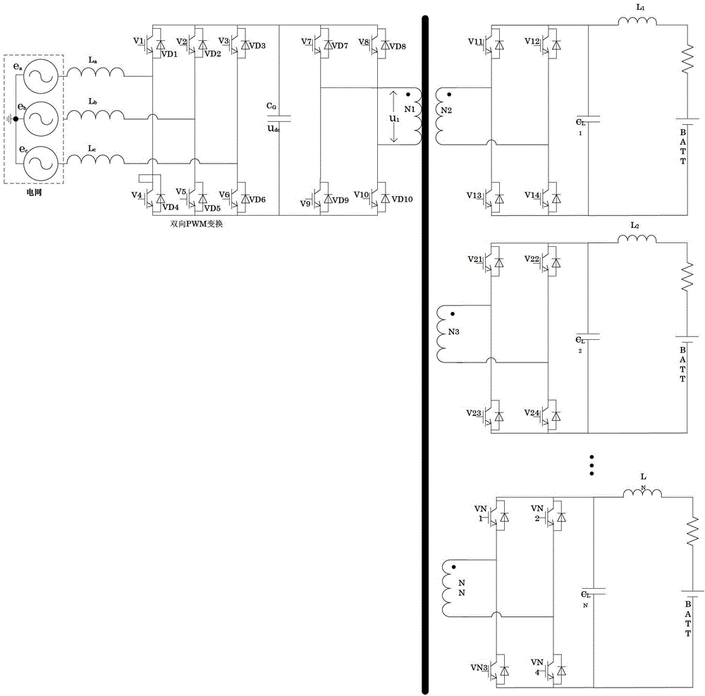
[0028] Such as figure 1 Shown is a circuit diagram of the present invention, which includes: a first-level circuit, a second-level circuit, and a DSP controller.

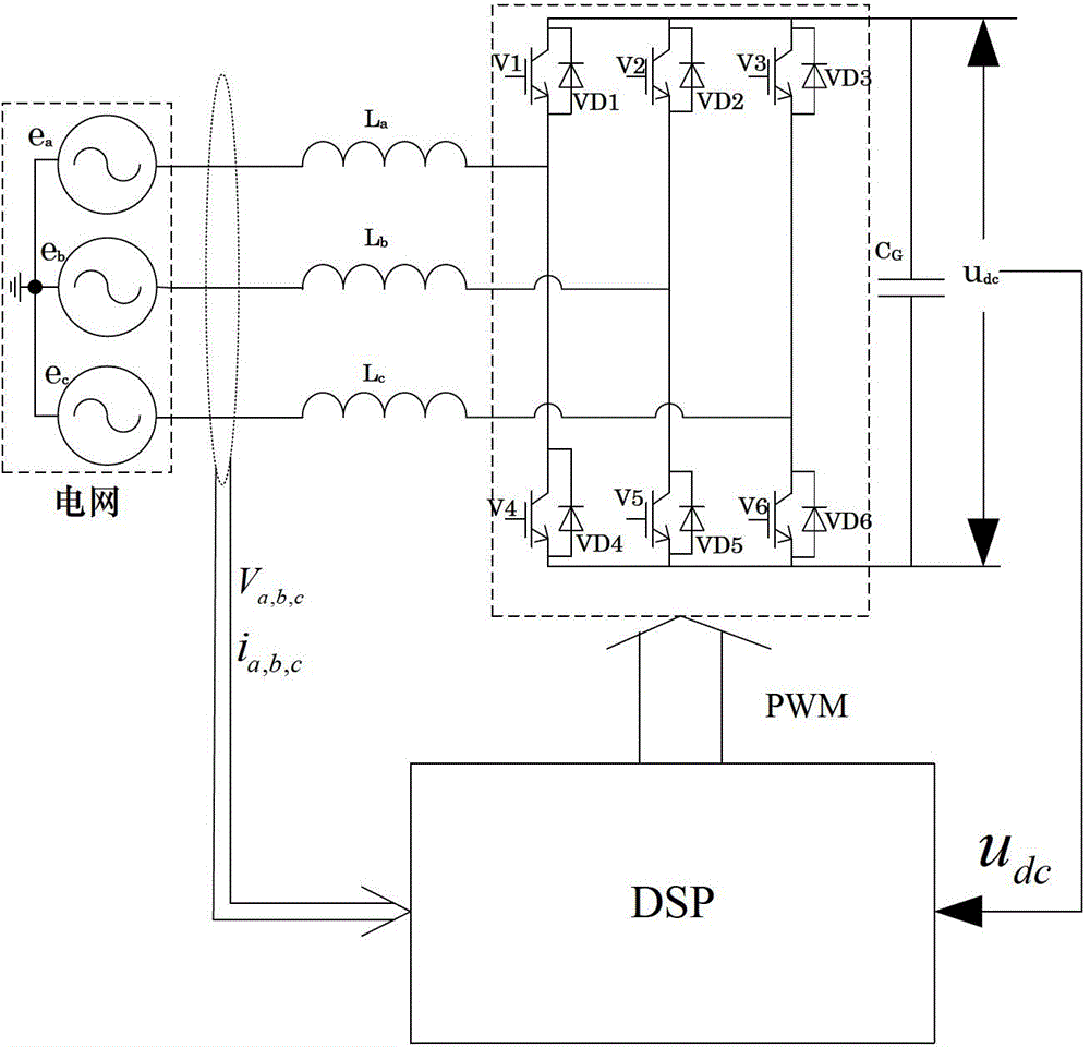
[0029] Such as figure 2 As shown, the first-stage circuit includes a three-phase AC grid (e a , E b , E c ), the filter inductance (L a , L b , L c ), inverter circuit. The inverter circuit is composed of six transistors V1, V2, V3, V4, V5, V6 of the three-phase bridge. After the three phases of the power supply are connected in a star shape, the output of each phase is passed through the filter inductor L a , L b , L c Then connect to the three bridge arms of the three-phase bridge.

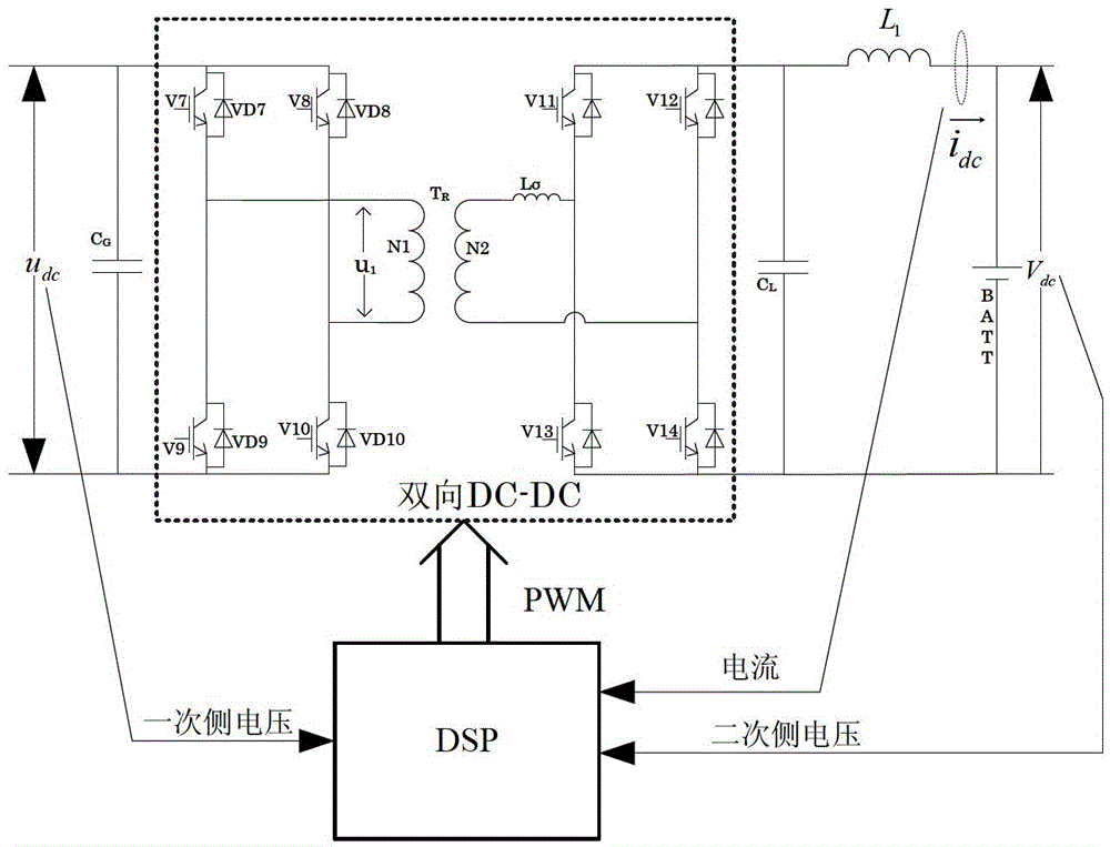
[0030] Such as image 3 As shown, the second stage circuit includes a first DC-DC conversion circuit, a transformer, a second DC-DC conversion circuit, a filter capacitor, and a battery;

[0031] The high-voltage bus and low-voltage bus of th...


PUM


Abstract

The invention relates to storage battery charge and discharge circuit topology which comprises a first stage of circuit, a second stage of circuit and a digital signal processor (DSP) controller; the first stage of circuit comprises three phases of alternating current power grids and an inverter circuit; the inverter circuit is provided with six transistors of a three-phase bridge, and the second stage of circuit comprises a first conversion circuit, a transformer, a second conversion circuit and a battery; and the DSP controller controls the output voltage, the output current and the switching direction of the inverter circuit and two direct current-direct current (DC-DC) conversion circuits so as to control the charge or the discharge of the whole circuit. After the device is adopted, charge and discharge with unit power factor can be realized for a power grid side; the pollution to the power grid is little; through a certain control method, a pulse width modulation (PWM) rectifier can realize a scalable vector graphics (SVG) function; the output of a wide voltage scope can be realized; and the charge and discharge efficiency is higher.

Description

Technical field: [0001] The invention belongs to the electrical field, and specifically relates to a battery charging and discharging circuit topology. Background technique: [0002] The previous charging and discharging devices generally used several topologies mentioned in the article "Qin Haihong, Zhu Deming and Yan Yangguang, Design Considerations for Electric Vehicle Charger Circuit Topology. Power Supply Technology Application, 2004(2): Page 97-104." The topology rarely achieves both the charging and discharging (energy feedback to the grid) functions of the battery. [0003] Take the resonant converter topology mentioned in this article as an example, such as Figure 4 As shown, the H-bridge soft switching is realized through LC resonance, and then the charging control is realized through diode rectification, which cannot discharge the power grid. Summary of the invention: [0004] In view of the above-mentioned defects or deficiencies, the purpose of the present invention is...

Claims


Application Information

Patent Timeline
IPC IPC(8): H02J7/02H02J7/04
Inventor 王跃郭海平黄珺高远
Owner XIAN ACTIONPOWER ELECTRIC
Why Eureka
Try Eureka