Canopy shelter brackets

a canopy frame and canopy technology, applied in tents/canopies, building types, constructions, etc., can solve the problems of reducing the structural integrity of the frame, reducing making the frame more difficult to expand and collapse. , to achieve the effect of reducing the flexibility of the canopy frame, and reducing the structural integrity of the fram

Active Publication Date: 2016-03-08
SHELTERLOGIC
View PDF25 Cites 10 Cited by
  • Summary
  • Abstract
  • Description
  • Claims
  • Application Information

AI Technical Summary

Benefits of technology

[0009]One aspect of the present invention is the realization that the bracket utilized to maintain the generally perpendicular orientation between cross members adds unwanted flexibility to the canopy frame, creating misalignment, excessive friction, and twisting of the canopy frame. This flexibility reduces the structural integrity of the frame as well as making the frame more difficult to expand and collapse. Thus, there exists need for an improved bracket design.
[0010]One non-limiting embodiment of the present invention includes an F-bracket comprising an inner portion, an intermediate portion, a first outer portion, and a second outer portion. The F-bracket pivotally engages both sides of an outer cross member, increasing the structural integrity and stiffness of the canopy frame and helping to maintain proper alignment of the cross members and making expansion and collapse of the canopy frame much smoother and easier.
[0011]Another non-limiting embodiment of the present invention includes an S-bracket comprising an inner portion, an intermediate portion, a first outer portion, and a second outer portion. The S-bracket pivotally engages both sides of an outer cross member, increasing the structural integrity and stiffness of the canopy frame and helping to maintain proper alignment of the cross members and making expansion and collapse of the canopy frame much smoother and easier.

Problems solved by technology

This flexibility reduces the structural integrity of the frame as well as making the frame more difficult to expand and collapse.

Method used


Image

  • Canopy shelter brackets
  • Canopy shelter brackets
  • Canopy shelter brackets

Examples


Embodiment Construction

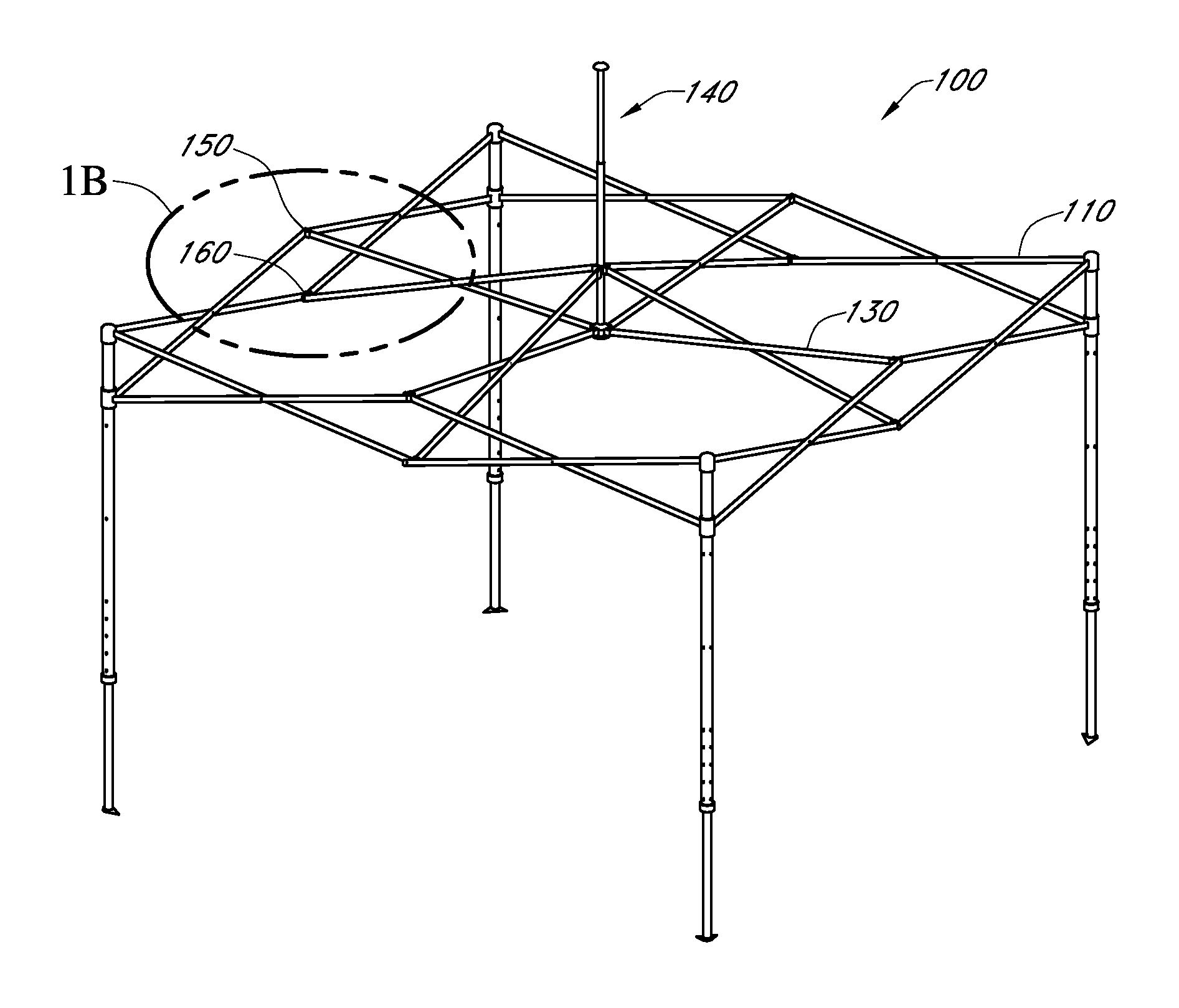
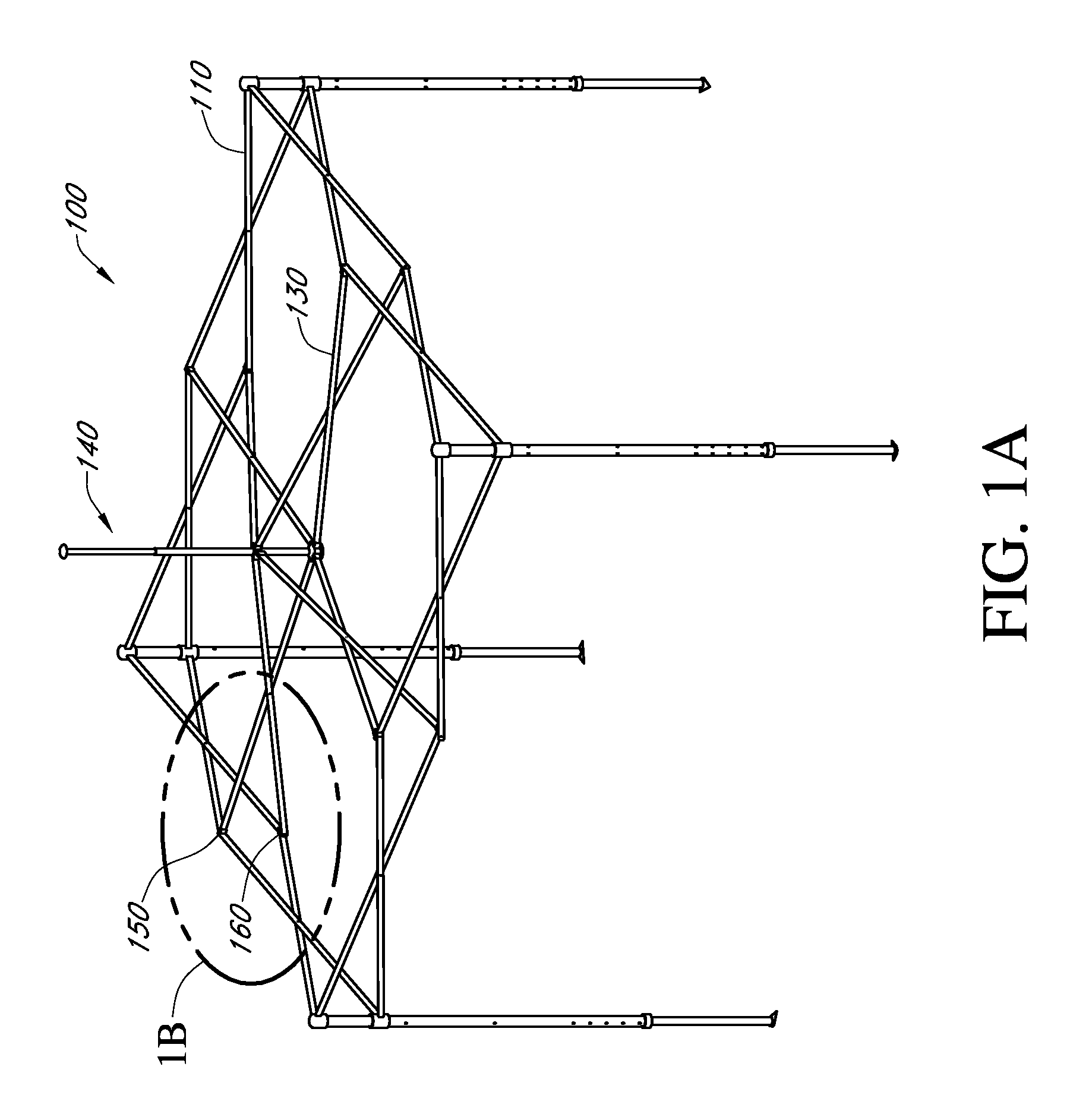
[0027]FIG. 1A illustrates a perspective view of one type of collapsible canopy frame 100. In one embodiment, the collapsible canopy frame 100 comprises a plurality cross members 110, 130 arranged and pivotally coupled such that the canopy frame 100 may be expanded and collapsed between an expanded state and a collapsed state. One embodiment of a canopy frame is described in U.S. Patent Publication No. 2009 / 0071521, to Sy-Facunda, the entirety of which is hereby incorporated by reference herein. In one embodiment, the canopy frame comprises an interior support or lift tube (e.g., a center support or center lift tube 140) configured to support an interior portion (e.g., the center) of the canopy cover (not illustrated) in an expanded state. In a square canopy, the interior support may be a center support. In a rectangular canopy, the interior support can be off-center. In particular, multiple interior supports can be provided in a rectangular canopy, with the interior supports often c...


PUM


Abstract

A canopy shelter bracket for increased structural integrity. The canopy shelter bracket can include an inner portion, an intermediate portion, a first outer portion, and a second outer portion integrally connected to form a generally “F” shape or an “S” shape. The inner portion, first outer portion, and / or the second outer portion can include holes for receiving a fastener therethrough to fasten the brackets to cross members. A single fastener can be used to fasten multiple cross members to the bracket. The first and / or second outer portions can additionally serve to space apart a first cross member from a second cross member.

Description

INCORPORATION BY REFERENCE TO PRIORITY APPLICATION[0001]The present application claims priority to U.S. Provisional Application No. 61 / 750,235 filed Jan. 8, 2013, entitled CANOPY SHELTER BRACKETS, the entire contents of which are hereby expressly incorporated by reference herein and made a part of the present disclosure.BACKGROUND OF THE INVENTION[0002]1. Field of the Invention[0003]The present invention relates to collapsible canopy frames and, in particular, canopy frames having improved connection brackets.[0004]2. Description of the Related Art[0005]Canopy shelters with collapsible frames are commonly used to provide portable shelter for outdoor activities such as camping, picnicking, parties, weddings, and more. Such collapsible canopy shelters typically comprise a canopy cover and a canopy frame configured to stand alone when in an expanded or deployed state and to collapse into a collapsed state for storage and transport.[0006]While conventional canopy shelters are useful for...

Claims


Application Information

Patent Timeline
Patent Type & Authority Patents(United States)
IPC IPC(8): E04H15/50E04H15/32
CPCE04H15/50E04H15/32
Inventor LOVLEY, II, JACK B.KLINGL, JOSEPH C.GROENHUYZEN, MARK
Owner SHELTERLOGIC
Why Eureka
Try Eureka