Multilayer stack with overlapping harmonics for wide visible-infrared coverage

a multi-layer, visible-infrared technology, applied in the direction of mirrors, instruments, spectral modifiers, etc., can solve the problem that the stack may not provide the 3sup>rd /sup>order reflection band

Active Publication Date: 2016-03-08
3M INNOVATIVE PROPERTIES CO
View PDF31 Cites 15 Cited by
  • Summary
  • Abstract
  • Description
  • Claims
  • Application Information

AI Technical Summary

Problems solved by technology

In some cases, the stack may not provide the 3rd order reflection band.

Method used


Image

  • Multilayer stack with overlapping harmonics for wide visible-infrared coverage
  • Multilayer stack with overlapping harmonics for wide visible-infrared coverage
  • Multilayer stack with overlapping harmonics for wide visible-infrared coverage

Examples


Embodiment Construction

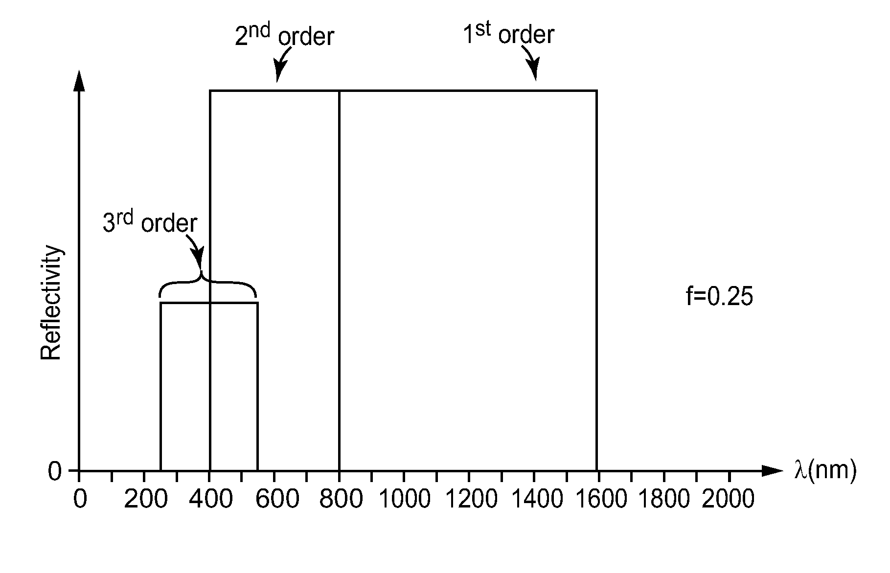
[0050]As mentioned above, we disclose here inter alia optical articles such as multilayer optical films and film combinations in which at least one microlayer stack or packet provides multiple harmonic reflection bands at a design angle of incidence, including a 2nd order reflection band and a 1st order reflection band, and the 2nd order reflection band overlaps or substantially overlaps the 1st order reflection band and / or a 3rd order reflection band, if present, to provide a single wide reflection band that covers at least a portion of visible and infrared wavelengths. The relationships provided in this disclosure between reflection bands of a given stack, and between reflection bands of different stacks, rely upon a clear and precise definition for what a reflection band is and what some of its characteristic features are, particularly, the spectral location of the opposed boundaries or edges of the reflection band. Such definitions are provided further below for purposes of this...


PUM


Abstract

A broadband mirror, polarizer, or other reflector includes at least one stack of microlayers. Microlayers in the stack are arranged into optical repeat units. At a design angle of incidence such as normal incidence, the stack provides a 1st order reflection band, a 2nd order reflection band, and optionally a 3rd order reflection band. The 2nd order reflection band overlaps, or substantially overlaps, the 1st and / or 3rd order reflection bands to form a single wide reflection band. The wide reflection band may include the 2nd and 1st but not a 3rd order reflection band, or the 2nd and 3rd but not the 1st order reflection band, or it may include the 1st, 2nd, and 3rd order reflection bands, as well as still higher order reflection bands. The wide reflection band may cover at least a portion of visible and infrared wavelengths.

Description

FIELD[0001]The present disclosure relates to, among other things, multilayer optical films whose reflection and transmission characteristics are determined in large part by constructive and destructive interference of light reflected from interfaces within a stack of microlayers. The disclosure also relates to articles and systems incorporating such optical films, and methods of making and using such films.BACKGROUND[0002]Multilayer optical films are known. Such films can incorporate a large number of thin layers of different light transmissive materials, the layers being referred to as microlayers because they are thin enough so that the reflection and transmission characteristics of the optical film are determined in large part by constructive and destructive interference of light reflected from the layer interfaces. Depending on the amount of birefringence (if any) exhibited by the individual microlayers, and the relative refractive index differences for adjacent microlayers, and...

Claims


Application Information

Patent Timeline
Patent Type & Authority Patents(United States)
IPC IPC(8): F21V9/04G02B5/28G02B5/26G02B5/08G02B5/30
CPCG02B5/0841G02B5/0816G02B5/281G02B5/287G02B5/3041G02B5/26
Inventor KIVEL, EDWARD J.NEVITT, TIMOTHY J.WEBER, MICHAEL F.
Owner 3M INNOVATIVE PROPERTIES CO
Why Eureka
Try Eureka