
Reorientation of cardiac images

a cardiac image and reorientation technology, applied in image enhancement, instruments, x/gamma/cosmic radiation measurement, etc., can solve the problems of unsatisfactory results of known automatic reorientation methods, errors in further processing of image data, and inability to directly detect the location of body features of pet or spect imaging

Active Publication Date: 2016-03-15
SIEMENS MEDICAL SOLUTIONS USA INC
View PDF8 Cites 1 Cited by
  • Summary
  • Abstract
  • Description
  • Claims
  • Application Information

AI Technical Summary

Benefits of technology

[0018]An object of the present invention is to provide a method for reorienting images, such as cardiac images, wherein the disadvantages of known procedures as described above are avoided, or at least minimized.

Problems solved by technology

PET or SPECT imaging does not directly detect the location of body features.
This can lead to errors in further processing of the image data, especially when it comes to comparing multiple datasets.
Known automatic reorientation methods have been found to generate unsatisfactory results.

Method used


Image

  • Reorientation of cardiac images
  • Reorientation of cardiac images
  • Reorientation of cardiac images

Examples


Embodiment Construction

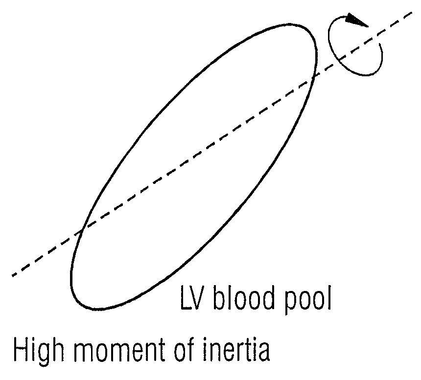
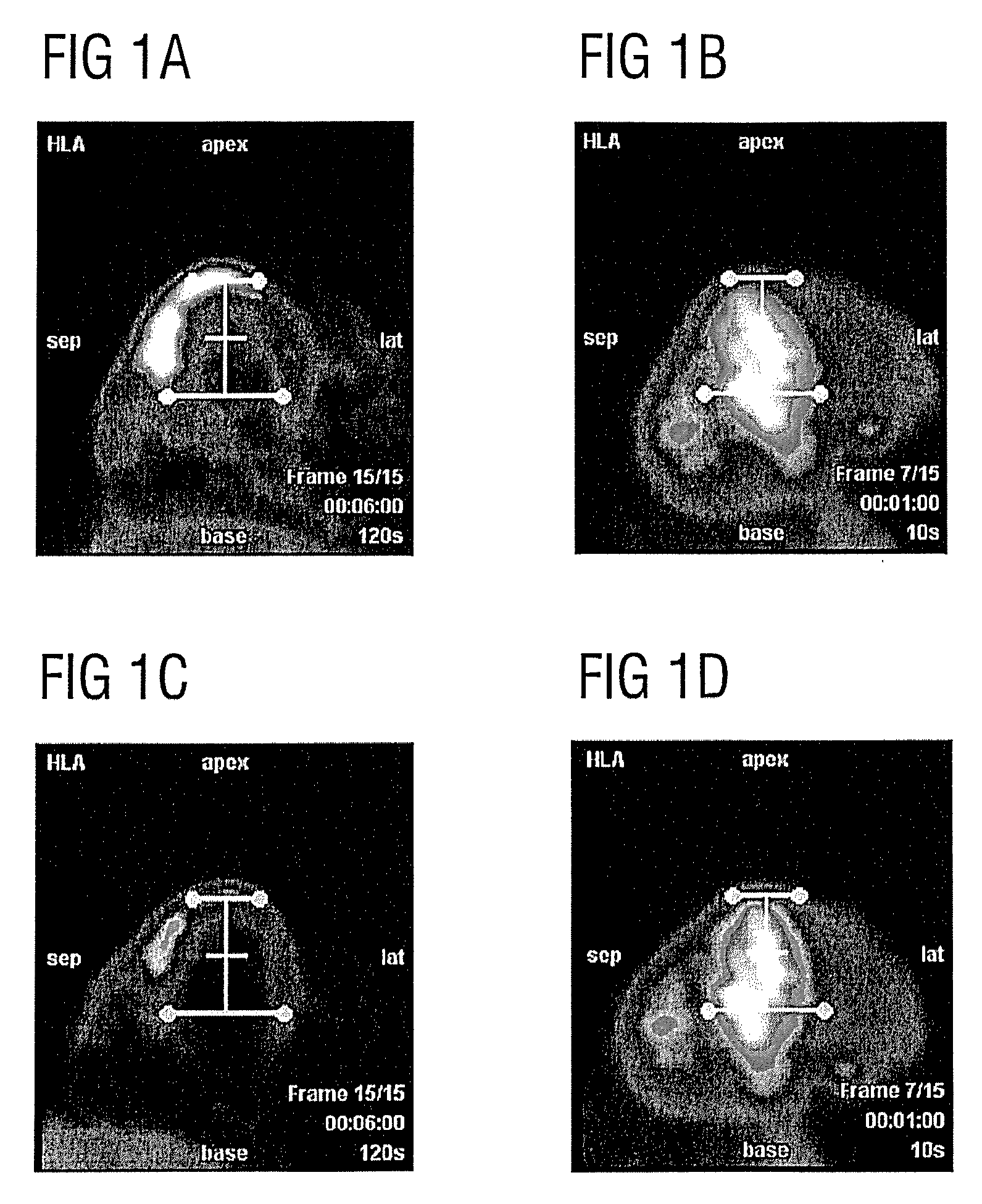
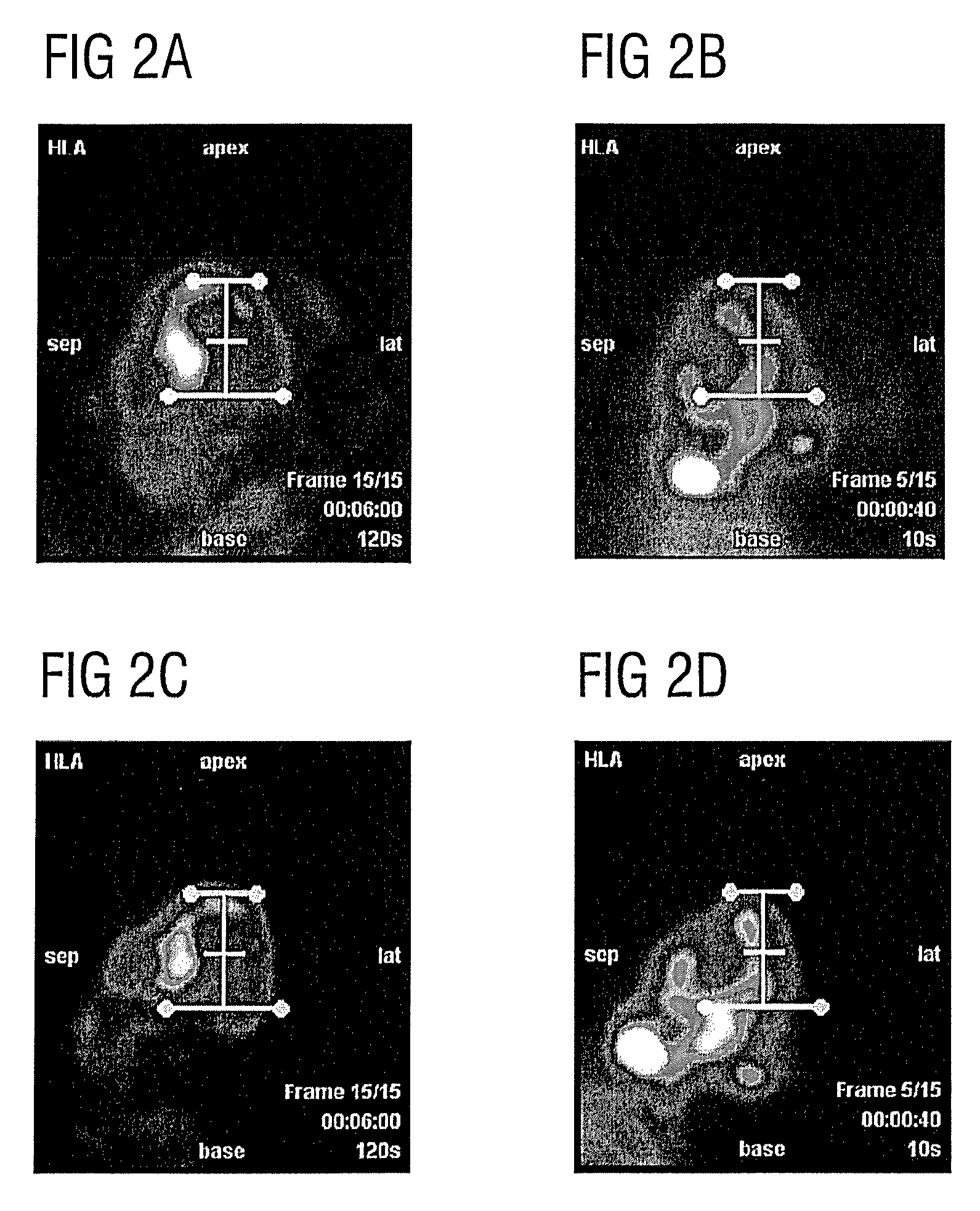
[0029]The present invention accordingly provides a method that identifies automatically the early frame blood pool image corresponding to a late frame image, and compares reorientation angles that have been found, either manually or automatically, from the late frame to a major axis found in the blood pool image.

[0030]A thresholding step may be used to determine whether the reorientation angle determined from the late frame differs significantly from the major axis identified in the early, blood pool, image. If a significant difference is identified, being in excess of a defined threshold, a warning is given to a user. Optionally, the blood pool image may be displayed for verification and new reorientation angle(s) may be suggested.

[0031]The early frame blood pool image which is automatically identified in the method of the present invention may be selected by identifying the peak frame containing the blood pool image. This image is preferably displayed either in the cardiac view or...


PUM


Abstract

In a method for estimating an orientation of a cardiac long axis from corresponding early frame and late frame images implemented in a computerized processor, a bounding box of the myocardium is defined in the late frame image and the bounding box is applied to the early frame image. A main axis of the image of the early frame within the bounding box is estimated, and the image of the early frame is oriented according to the estimated main axis. A main axis of the image of the late frame within the bounding box is also estimated, and the late frame image is reoriented according to the estimated main axis. The estimated main axis of the early frame to the estimated main axis of the late frame are compared, and in attribute of the comparison result is made available as an output from the processor.

Description

BACKGROUND OF THE INVENTION[0001]1. Field of the Invention[0002]The present invention concerns a method for reorienting cardiac images that are among a number of successively obtained cardiac images, and in particular to such a method that is implemented in a computerized processor.[0003]2. Description of the Prior Art[0004]Images of the heart for medical diagnosis may be produced using a PET (Positron Emission Tomography) imaging modality or SPECT (Single Particle Emission Computed Tomography) imaging modality. PET or SPECT imaging does not directly detect the location of body features. Rather, a tracer is introduced into a patient's bloodstream, and the location and density of the tracer is detected. An effect of this is that early images show the location of blood, carrying the tracer. Later images show the position of muscle tissue such as myocardium, once tracer has been absorbed into the muscle tissue. The heart may accordingly be imaged in two distinct phases—early frames, wh...

Claims


Application Information

Patent Timeline
Patent Type & Authority Patents(United States)
IPC IPC(8): G06K9/00G06T7/60G06T7/00
CPCG06T7/0016G06T7/0044G06T7/608G06T2207/10104G06T2207/10108G06T2207/30048G06T7/74G06T7/68G01T1/2985G06T2210/12Y10S378/901
Inventor BOND, SARAHPAN, XIAO-BO
Owner SIEMENS MEDICAL SOLUTIONS USA INC
Learn More