
Calibration device for mass flow meters

a mass flow meter and calibration device technology, applied in the direction of structural/machine measurement, material analysis using sonic/ultrasonic/infrasonic waves, and geological measurements, can solve the problems of inability to produce steady flow in the calibration device, and the temperature measurement device only provides selective temperature information, so as to achieve highly accurate detection of temperature and avoid calibration device disadvantages

Inactive Publication Date: 2013-09-10
KRONE GMBH
View PDF12 Cites 0 Cited by
  • Summary
  • Abstract
  • Description
  • Claims
  • Application Information

AI Technical Summary

Benefits of technology

This approach ensures disturbance-free and highly accurate temperature measurement, allowing for quick detection of temperature changes and average temperature values, reducing measurement errors and improving calibration precision.

Problems solved by technology

Measurement tolerances always impact one of the parties in trade and they usually impact the distributor.
Secondly, the temperature of the medium also substantially influences the calibration device.
However, the invasive temperature probe has the disadvantage that the flow at the measurement point and downstream from the measurement point have substantial disturbances such that the flow in the calibration device cannot be produced as steadily, in total, as is necessary for a highly accurate measurement.
A further disadvantage is that an invasive temperature-measuring device only provides selective temperature information, which does not allow the measurement of temperatures changing along a flow profile, i.e., the identification of a temperature profile.
However, this is very disadvantageous because the number of disturbances induced in the flow to be measured is then increased.

Method used


Image

  • Calibration device for mass flow meters
  • Calibration device for mass flow meters
  • Calibration device for mass flow meters

Examples


Embodiment Construction

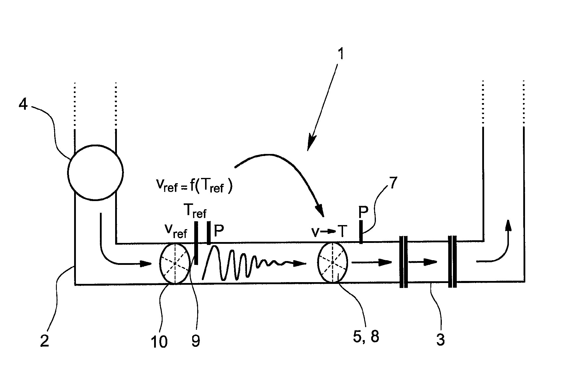
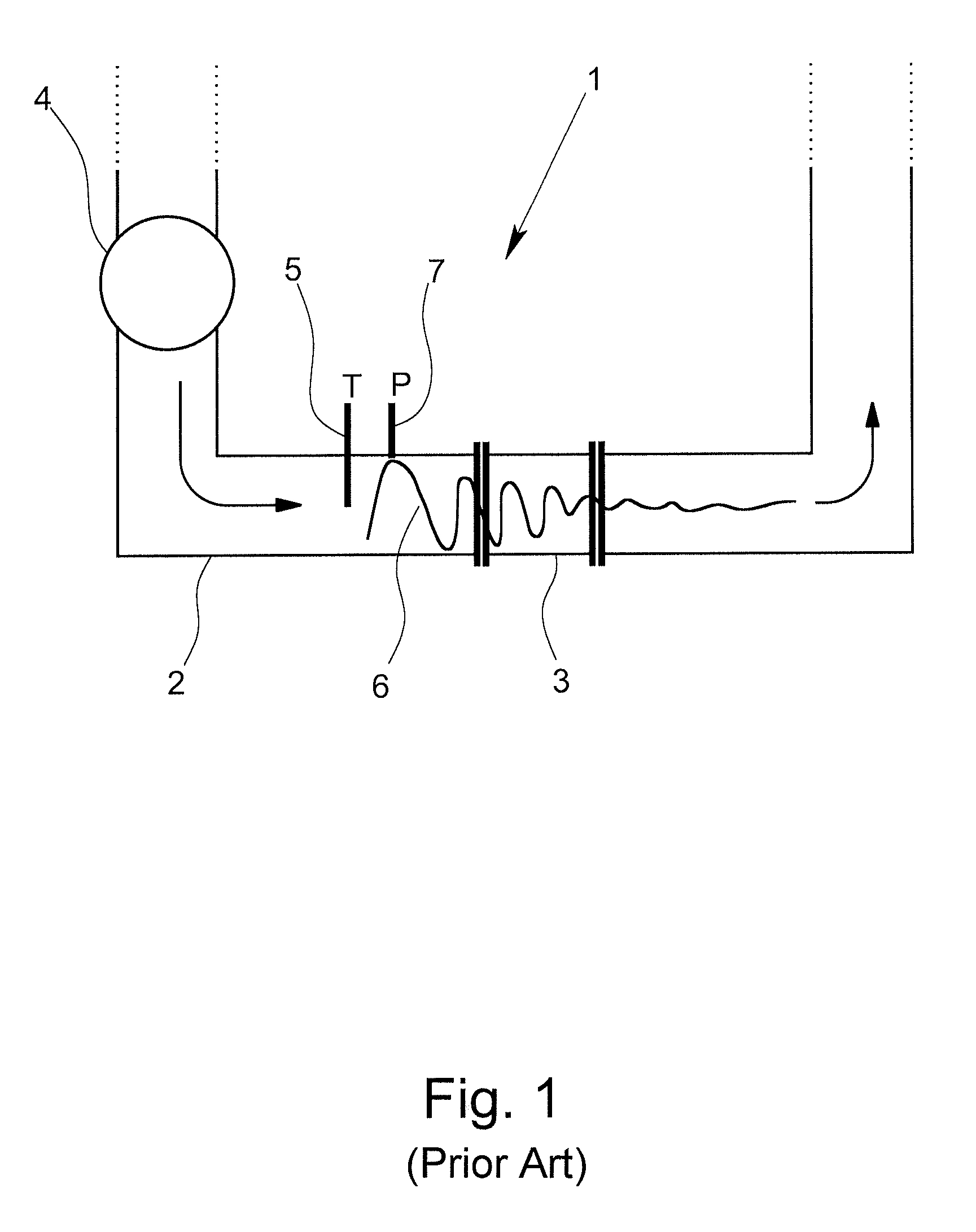
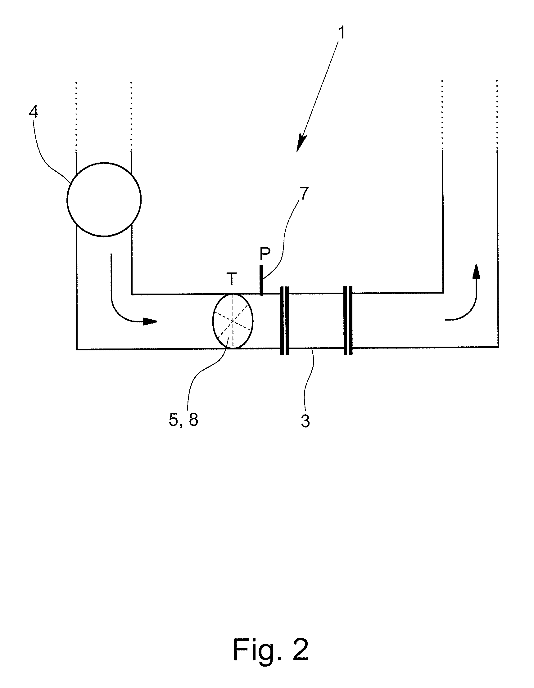
[0039]In FIG. 1, a known calibration device 1 from the related art is shown schematically. The calibration device has a test piece measuring section 2 in which a mass flow meter test piece 3 to be calibrated can be inserted and is presently inserted. The calibration device 1 additionally has a device 4 for creating a flow of a medium through the test piece measuring section 2. By way of non-limiting example, the device 4 can be a pump. Furthermore, the calibration device 1 has a temperature-measuring device 5 in the test piece measuring section 2 that is in immediate proximity to the mass flow meter test piece 3. The temperature measuring device 5 serves to detect the temperature of the medium.

[0040]The temperature-measuring device 5 in FIG. 1 is an invasive temperature-measuring sensor that extends into the volume of the test piece measuring section 2. For example, the temperature-measuring device 5 can be designed as an enclosed PT100 resistance element. The temperature measuremen...


PUM

PropertyMeasurementUnit
areaaaaaaaaaaa
temperatureaaaaaaaaaa
ultrasonic temperature-aaaaaaaaaa

Abstract

A calibration device for mass flow meters including a test piece measuring section into which the mass flow meter test piece to be calibrated can be inserted, a device for creating a flow of a medium through the test piece measuring section and a temperature-measuring device positioned in the test piece measuring section for detecting the temperature of the medium. The temperature-measuring device is position in the flow such that the flow is disturbed as little as possible, while at the same time being capable of highly-accurate detection of the temperature of the flowing medium. In particular, the temperature-measuring device is an ultrasonic temperature-measuring device that is configured to emit an ultrasonic signal into the medium and determine the temperature of the medium by measuring a speed of the emitted ultrasonic signal.

Description

BACKGROUND OF THE INVENTION[0001]1. Field of Invention[0002]The invention relates to a calibration device for mass flow meters and a method for calibrating a mass flow meter using such a calibration device, and more particularly, to a calibration device having at a test piece measuring section, a device for creating a flow of a medium through the test piece measuring section and a temperature-measuring device in the test piece measuring section for detecting the temperature of the medium and a method for calibrating a mass flow meter using such a calibration device.[0003]2. Description of Related Art[0004]Calibration devices of the above-mentioned type have been known for a long time from the related art. Calibration serves the purpose of detecting the deviation of the measurement of the mass flow meter test piece from a standard value provided by the calibration device in order to calibrate the mass flow meter test piece using the deviation. Such calibration devices are also used i...

Claims


Application Information

Patent Timeline
Patent Type & Authority Patents(United States)
IPC IPC(8): G01N29/00
CPCG01F25/0007G01K13/02G01K11/24G01K2013/026G01K13/026G01F25/10
Inventor VAN BRAKEL, PIETER CORNELIS LEENDERTVAN BEKKUM, AART JAN
Owner KRONE GMBH
Learn More