Embolic protection aspirator

a technology of embolism protection and aspirator, which is applied in the field of intravascular devices, can solve the problems of blockage of blood flow to the tissue, thrombosis, and blood clots, and achieve the effect of increasing suction pressur

Active Publication Date: 2016-04-05
BOSTON SCI SCIMED INC
View PDF259 Cites 5 Cited by
  • Summary
  • Abstract
  • Description
  • Claims
  • Application Information

AI Technical Summary

Benefits of technology

[0007]In an alternate embodiment, the aspirating filter delivery catheter may further include an operable end cap at the distal opening of the elongated shaft for minimizing debris collection on the distal side of the filter while the catheter is being advanced to the target site.
[0010]In an alternate embodiment, the aspirating filter retrieval catheter may further include an inflatable balloon around the elongated shaft proximate the distal end of the shaft. The balloon may be fluidly coupled to an inflation / deflation lumen extending to proximate the proximal end of the retrieval catheter. While applying suction at the proximal end of the aspiration lumen of the elongated shaft, the balloon may be inflated to partially restrict or fully occlude blood flow, thereby potentially increasing the suction pressure for extracting the debris. The balloon may then be deflated.

Problems solved by technology

The dislodged material (e.g., plaque), known as emboli, may be sufficiently large to occlude downstream blood vessels, potentially blocking blood flow to tissue.
Additionally, blood clots, known as thrombi, may form and either be sufficiently large or grow over time and block a blood vessel should the thrombus become released into the bloodstream.

Method used


Image

  • Embolic protection aspirator
  • Embolic protection aspirator
  • Embolic protection aspirator

Examples


Embodiment Construction

[0018]The following detailed description should be read with reference to the drawings, in which like elements in different drawings are numbered in like fashion. Those skilled in the art will recognize that many of the examples provided could have suitable alternatives that may be utilized without departing from the spirit of the disclosed invention.

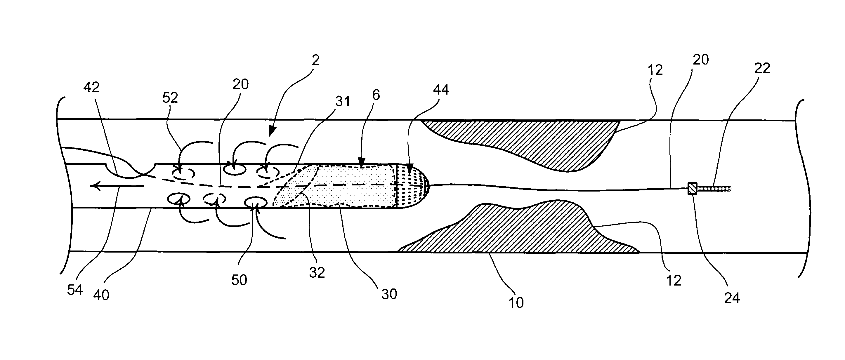
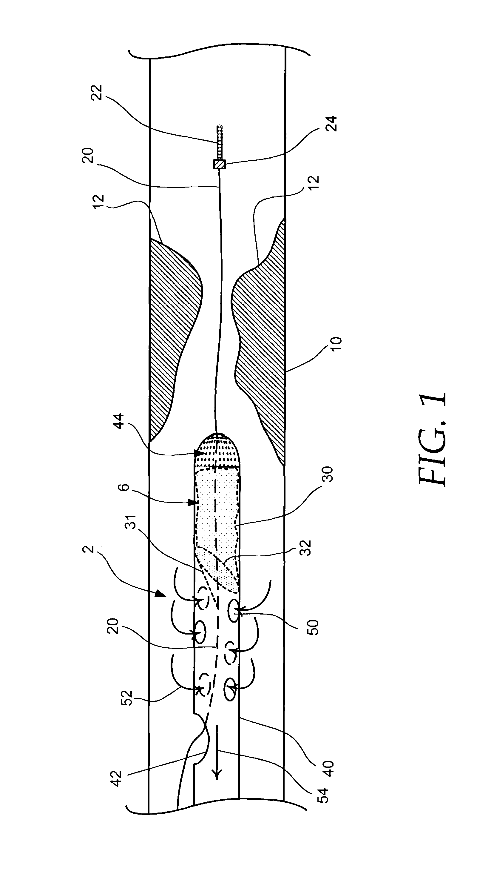
[0019]FIG. 1 is an illustration of an aspirating filter delivery catheter 2 in accordance with an embodiment of the present invention. Delivery catheter 2 includes an elongated shaft 40 having a proximal end (not shown) and a distal end, and contains a filtration device 6. An operable end cap 44 may be disposed on the distal end of elongated shaft 40. As shown in FIG. 1, elongated shaft 40, filtration device 6 and operable end cap 44 of delivery catheter 2 could be slidably coupled to a guide wire 20 therethrough. Catheter 2 can include a side guide wire opening 42.

[0020]Using well known percutaneous techniques, guide wire20, having a p...


PUM


Abstract

Embolic protection aspirators and methods for extracting debris from the vasculature during interventional procedures are provided. One such system may include an aspirating filter delivery catheter having a filtration device, an operable end cap, and a plurality of aspiration ports. The delivery catheter may be fluidly coupled to a suction providing means for extracting debris while traversing a target site for distal delivery of the filtration device. Another such system may include an aspirating filter retrieval catheter having an aspiration lumen and a balloon. The aspiration lumen may be fluidly coupled to a suction providing means for extracting debris from the filtration device prior to and / or during retrieval of the filtration device. By inflating the balloon to partially or fully restrict blood flow, suction pressure proximal of the filtration device may be increased to enhance debris extraction.

Description

FIELD OF THE INVENTION[0001]The present invention generally relates to intravascular devices used in interventional procedures. More specifically, the present invention relates to systems and methods for extracting debris, e.g., emboli, thrombi, etc., during the placement and retrieval of a blood permeable filtration device.BACKGROUND OF THE INVENTION[0002]Vascular procedures such as angioplasty, atherectomy, thrombectomy, stent placement, etc., used for treating occlusive vascular diseases cause material to dislodge from the inside wall of blood vessels and enter the bloodstream. The dislodged material (e.g., plaque), known as emboli, may be sufficiently large to occlude downstream blood vessels, potentially blocking blood flow to tissue. Additionally, blood clots, known as thrombi, may form and either be sufficiently large or grow over time and block a blood vessel should the thrombus become released into the bloodstream.[0003]Numerous interventional systems and methods that emplo...

Claims


Application Information

Patent Timeline
Patent Type & Authority Patents(United States)
IPC IPC(8): A61M29/00A61F2/01A61F2/958
CPCA61F2/013A61F2002/015A61F2002/018A61F2230/0006A61F2230/008A61F2230/0067A61F2230/0069A61F2/011
Inventor RAUKER, ROBERT M.SHAW, WILLIAM J.HANSEN, JAMES G.
Owner BOSTON SCI SCIMED INC
Why Eureka
Try Eureka