

Side mounted cowl vents for an over-the-road tractor vehicle
- Summary
- Abstract
- Description
- Claims
- Application Information
AI Technical Summary
Benefits of technology
Problems solved by technology
Method used
Image

Examples
Embodiment Construction
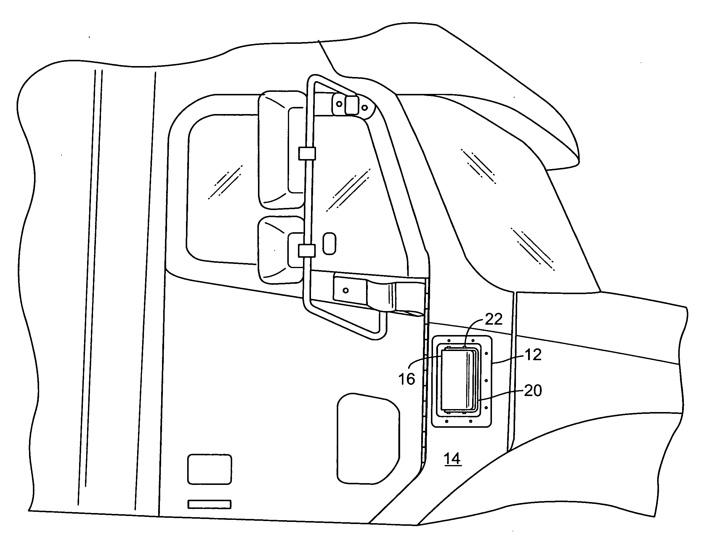
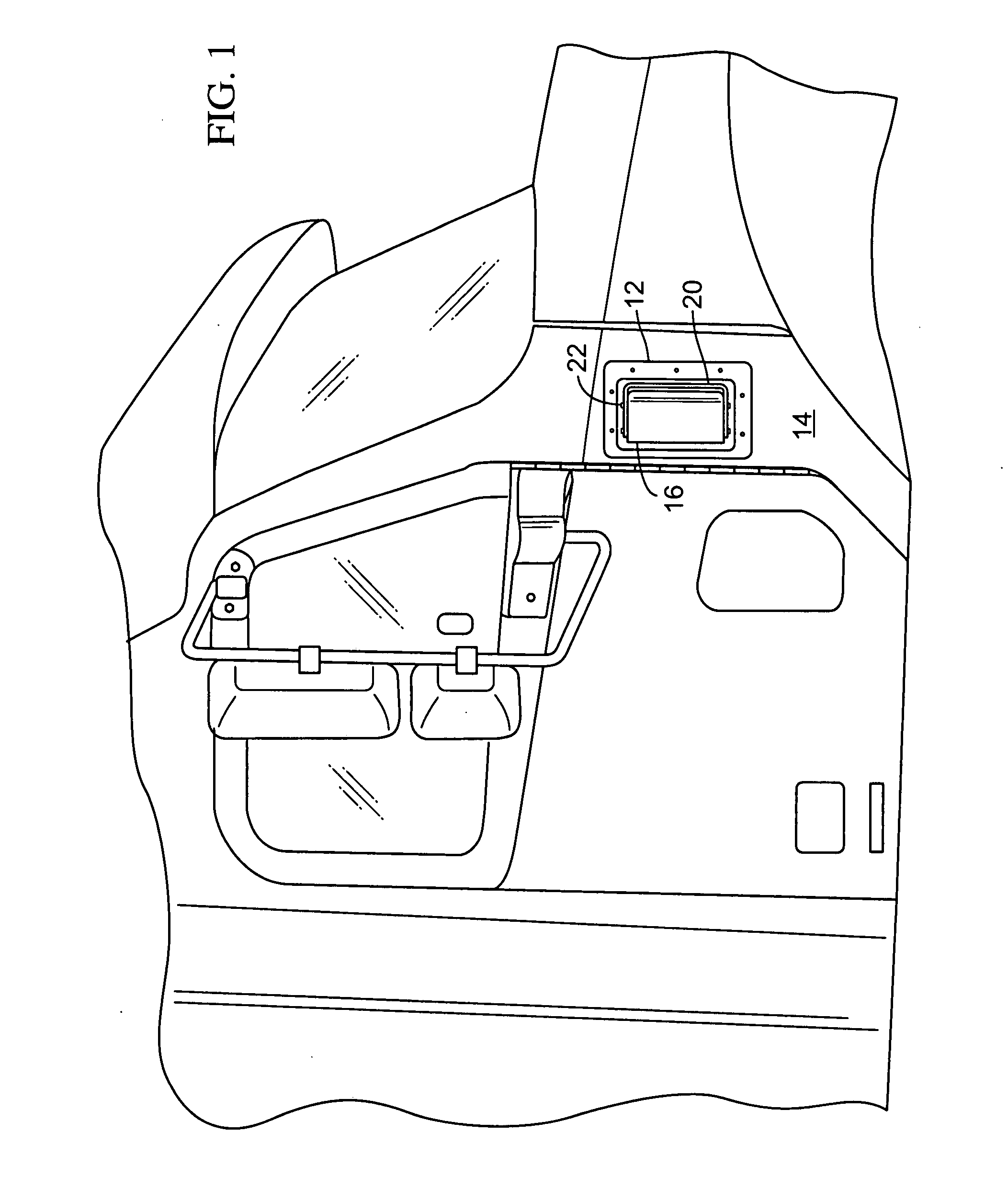
[0028]As seen in each of the figures the vent, generally 10 as shown is constructed of plastic, fiberglass, metal, carbon fiber, or other material that will provide a stiff and durable product. In one embodiment it is made up of a surround flange 12 that will be attached to a panel, such as the side cowl, 14 in FIG. 1 of a truck. Fastening and securing of the vent to the side cowl can be by any suitable fastener such as screw fasteners, nut and bolt fasteners, rivets, or adhesives. It can be “glassed in” using fiberglass as is well know in the trade.
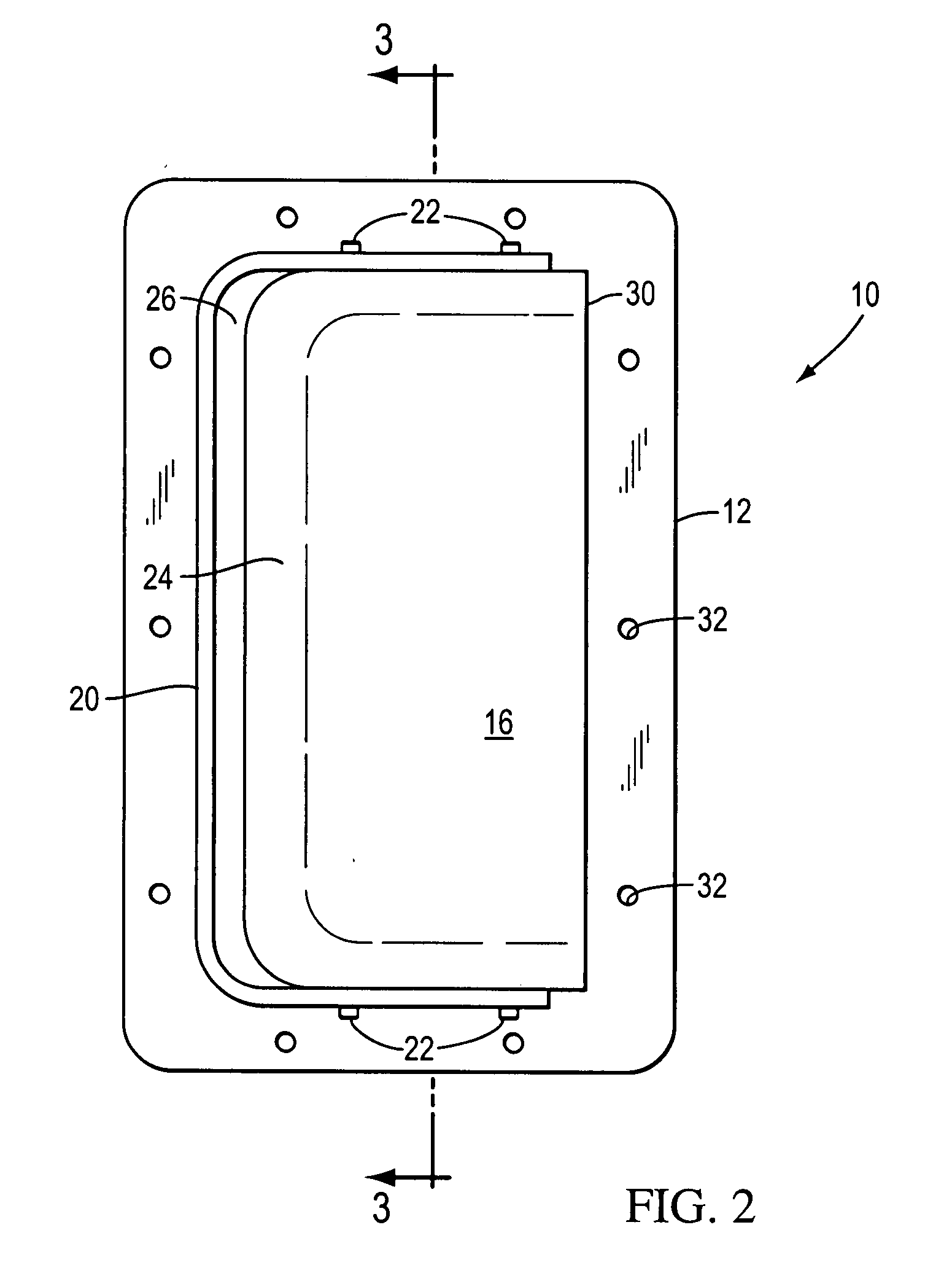
[0029]The vent 10 may include a deflector element 16 that is carried in the surround flange 12. In one embodiment the deflector element 16 fits inside a raised lip 20 or wall of the surround flange 12 and is secured in that location by fasteners 22.
[0030]The deflector element 16 has a curved leading portion 24 that would face the front of the host truck. The curved leading portion 24 may be spaced rearwardly from the raised lip 20 of the...
PUM
 Abstract
Description
Claims
Application Information