Plug connection for the direct electrical contacting of a circuit board

a technology for connecting plugs and circuit boards, which is applied in the direction of coupling device connections, coupling parts engagement/disengagement, two-part coupling devices, etc. it can solve the problems of easy optimization, unfavorable effect on spring dimensioning, and unfavorable effect on reducing the size of wire harness plugs

Active Publication Date: 2016-04-05
ROBERT BOSCH GMBH
View PDF10 Cites 8 Cited by
  • Summary
  • Abstract
  • Description
  • Claims
  • Application Information

AI Technical Summary

Benefits of technology

[0009]An objective of the present invention is to develop a plug connection of the species in such a way that a plug-side contact pressure spring may be omitted and the miniaturization of the plug may be increased further.
[0012]The omission, according to the present invention, of the “contact pressure reinforcement” hitherto provided on the plug yields in particular the following advantages:
[0018]The force buildup by the spring elements positioned in the plug receptacle occurs only at the very end of the plugging process. The plugging process may thus occur over a long travel path nearly without applying force. This fundamentally reduces the danger of damage to contact elements by the circuit board and its contact surfaces and facilitates the formation of the plug connection during the plugging process since the latter occurs in a region in which the contact pressure is not yet active.

Problems solved by technology

It is believed that this may entail the following disadvantages, however:The functional component “contact pressure reinforcement for the wire harness plug” has an unfavorable effect on a reduction of the size of the wire harness plug.Existing design approaches display an application of force on the structure of the wire harness plug that is not easy to optimize in practice.
Since wire harness plugs are normally made of plastic and are therefore subject to a permanent flow behavior as a function of temperature and stress, this aspect cannot be ignored.Existing design approaches have spring elements that already require a pretensioned contact pressure spring even in the case of a wire harness plug that has not been contacted.
This has an unfavorable effect on the dimensioning of the spring.Existing design approaches have layouts that require spring expansions that run counter to the expansions necessary in the event of a load (i.e. when the wire harness plug is plugged).
This has an unfavorable effect on the dimensioning of the contact pressure spring and the plug-in force.Existing design approaches have layouts, which, when applying the contact pressure force via the contact pressure spring, produce opposing forces or moments that counteract the actual contact pressure force.

Method used


Image

  • Plug connection for the direct electrical contacting of a circuit board
  • Plug connection for the direct electrical contacting of a circuit board

Examples


Embodiment Construction

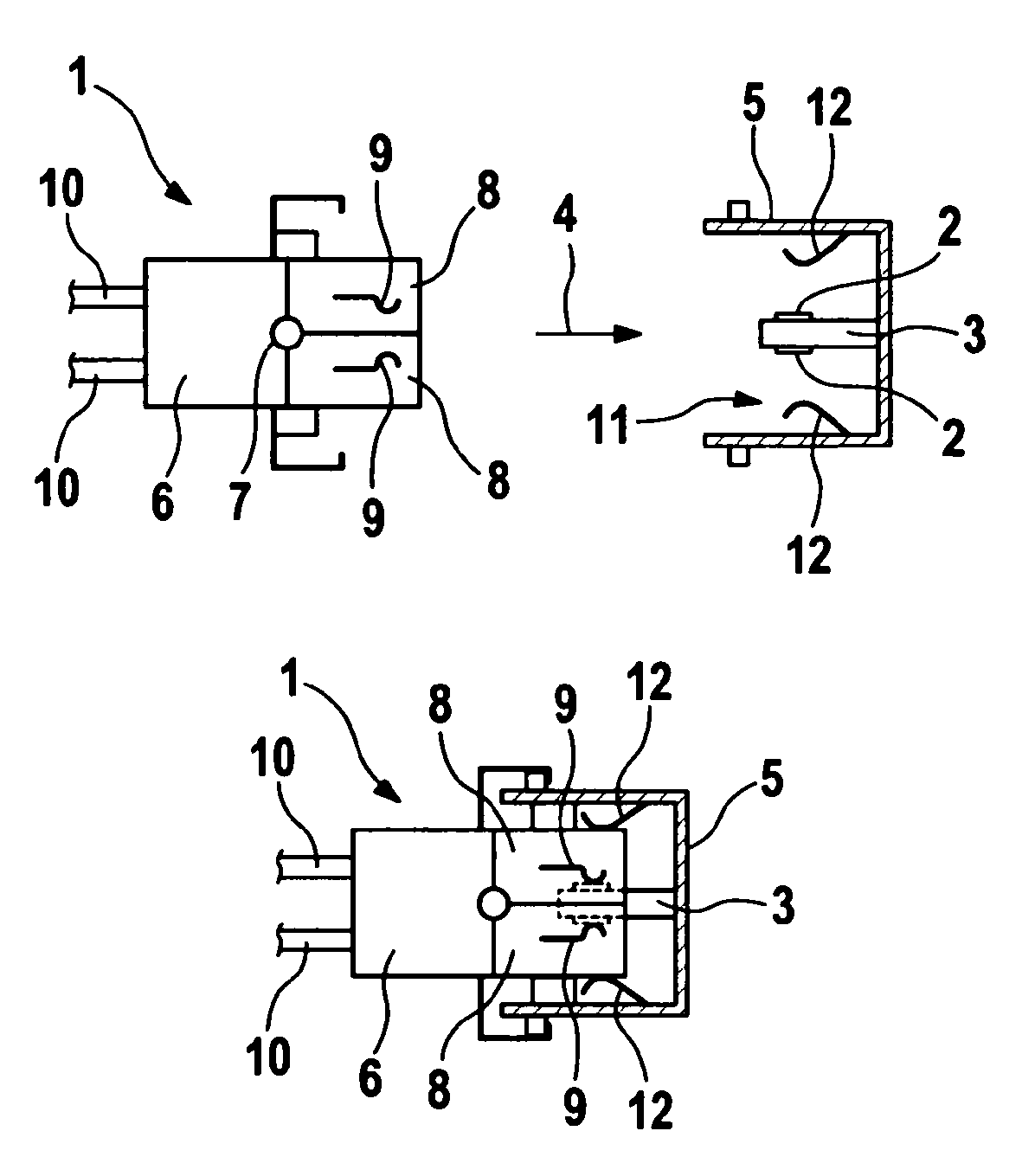
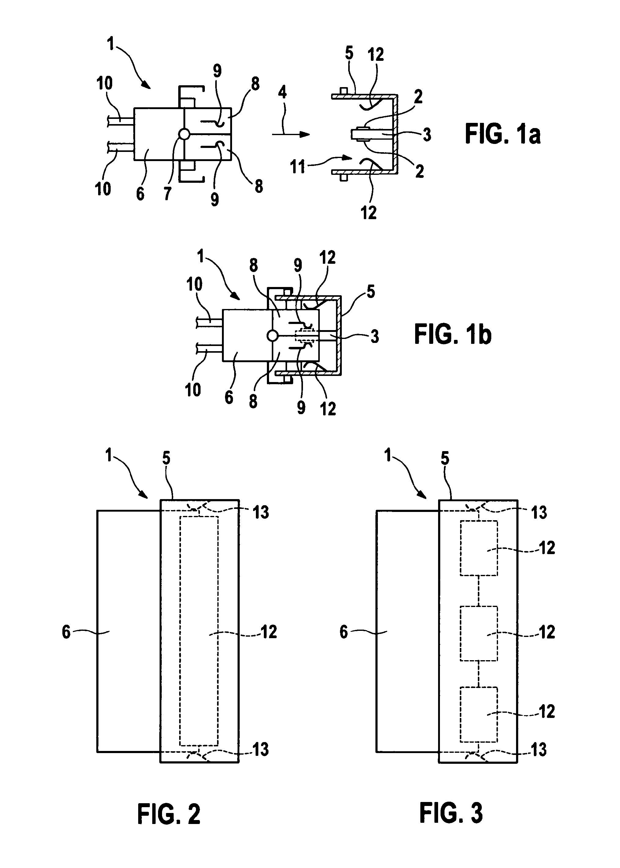
[0025]The plug connection shown in FIGS. 1a, 1b is configured for the direct electrical contacting of contact surfaces (“lands”) 2 on a circuit board 3 also referred to as a “control unit”, it being possible for the contact surfaces 2 to be provided on one or on both side(s) of circuit board 3.

[0026]A plug receptacle 5 of a plug shroud or a plug box, which is open in a plugging direction 4, is provided on circuit board 3, into which circuit board 3 extends in the area of its contact surfaces 2 against plugging direction 4. A plug (e.g. a wire harness plug) 6 is plugged into plug receptacle 5 in plugging direction 4, which has two contact carrier halves 8 that are connected to each other in a hinged manner at location 7. As shown in FIG. 1b, circuit board 3 is plugged in between the two contact carrier halves 8, which in the process electrically contact the contact surfaces 2 of circuit board 3 by their springy contact elements 9. The electric lines of wire harness plug 6 leading to ...


PUM


Abstract

In a plug connection for the direct electrical contacting of contact surfaces on a circuit board, having a plug receptacle associated with the circuit board, into which the circuit board extends, having a plug pluggable into the plug receptacle, which has a contact carrier having contact elements for the direct electrical contacting of the contact surfaces of the circuit board, and having a contact pressure spring device for pressing the contact elements of the contact carrier against the contact surfaces of the circuit board, the contact pressure spring device is provided in the plug receptacle.

Description

FIELD OF THE INVENTION[0001]The present invention is based on a plug connection for the direct electrical contacting of contact surfaces on a circuit board.BACKGROUND INFORMATION[0002]Control units are usually made up of a circuit board, on which electronic components are placed, and a housing. In engine control units, a male multipoint connector is usually mounted on the circuit board in order to establish the electrical connection between a wire harness plug and the circuit board. The male multipoint connector thus represents an additional component in the assembly of the control unit. So-called electrical direct contacts are also known in which the male multipoint connector is omitted and the individual poles of the wire harness plug are contacted directly on the circuit board. For this purpose, electrical contact surfaces (“lands”) are provided on the circuit board, which are contacted by contact elements, which are plugged into the wire harness plug.[0003]Direct plug connection...

Claims


Application Information

Patent Timeline
Patent Type & Authority Patents(United States)
IPC IPC(8): H01R13/66H01R12/50H01R13/62H01R12/72H01R13/193
CPCH01R13/6658H01R12/721H01R13/193H01R13/62H01R23/68H01R12/00H01R12/87
Inventor SELLMER, FRANKSCHMATZ, ULRICHSCHOENFELD, MICHAELBUSCHLE, HARTMUTREHBEIN, PETERKROECKEL, MARKUSSTEIN, JUERGENFLEIG, MICHAEL
Owner ROBERT BOSCH GMBH
Why Eureka
Try Eureka