String light connector

a technology of string lights and connectors, applied in the direction of coupling device connections, contact members penetrating/cutting insulation/cable strands, lighting and heating apparatus, etc., can solve the problems of time-consuming and laborious, process not only troublesome, etc., and achieve the effect of saving a considerable amount of time and effort wasted and enhancing production efficiency

Inactive Publication Date: 2016-04-05
LIN TE HUI
View PDF5 Cites 8 Cited by
  • Summary
  • Abstract
  • Description
  • Claims
  • Application Information

AI Technical Summary

Benefits of technology

[0005]A novel connector is provided herein so as to obviate the shortcomings of the prior art. According to the present invention, the installation of the connector can be conducted along with the installation of the lamps of a string light by an automated machine. The automated machine will strip the wir

Problems solved by technology

This process not only is troublesome, b

Method used


Image

  • String light connector
  • String light connector
  • String light connector

Examples


Embodiment Construction

[0018]The following descriptions are exemplary embodiments only, and are not intended to limit the scope, applicability or configuration of the invention in any way. Rather, the following description provides a convenient illustration for implementing exemplary embodiments of the invention. Various changes to the described embodiments may be made in the function and arrangement of the elements described without departing from the scope of the invention as set forth in the appended claims.

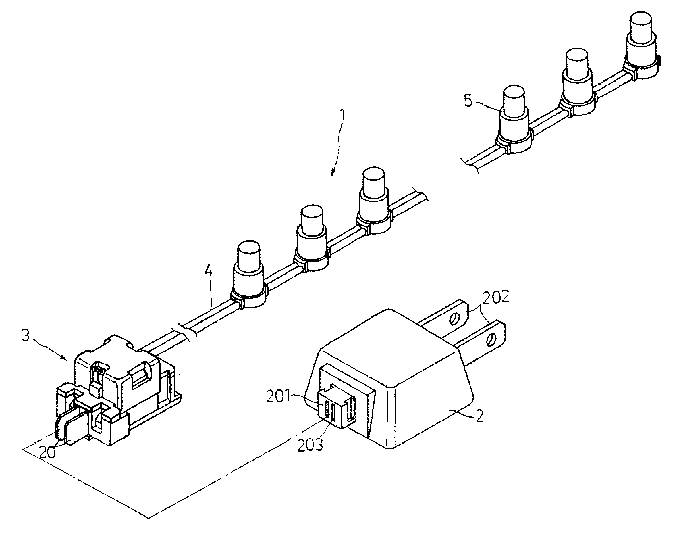
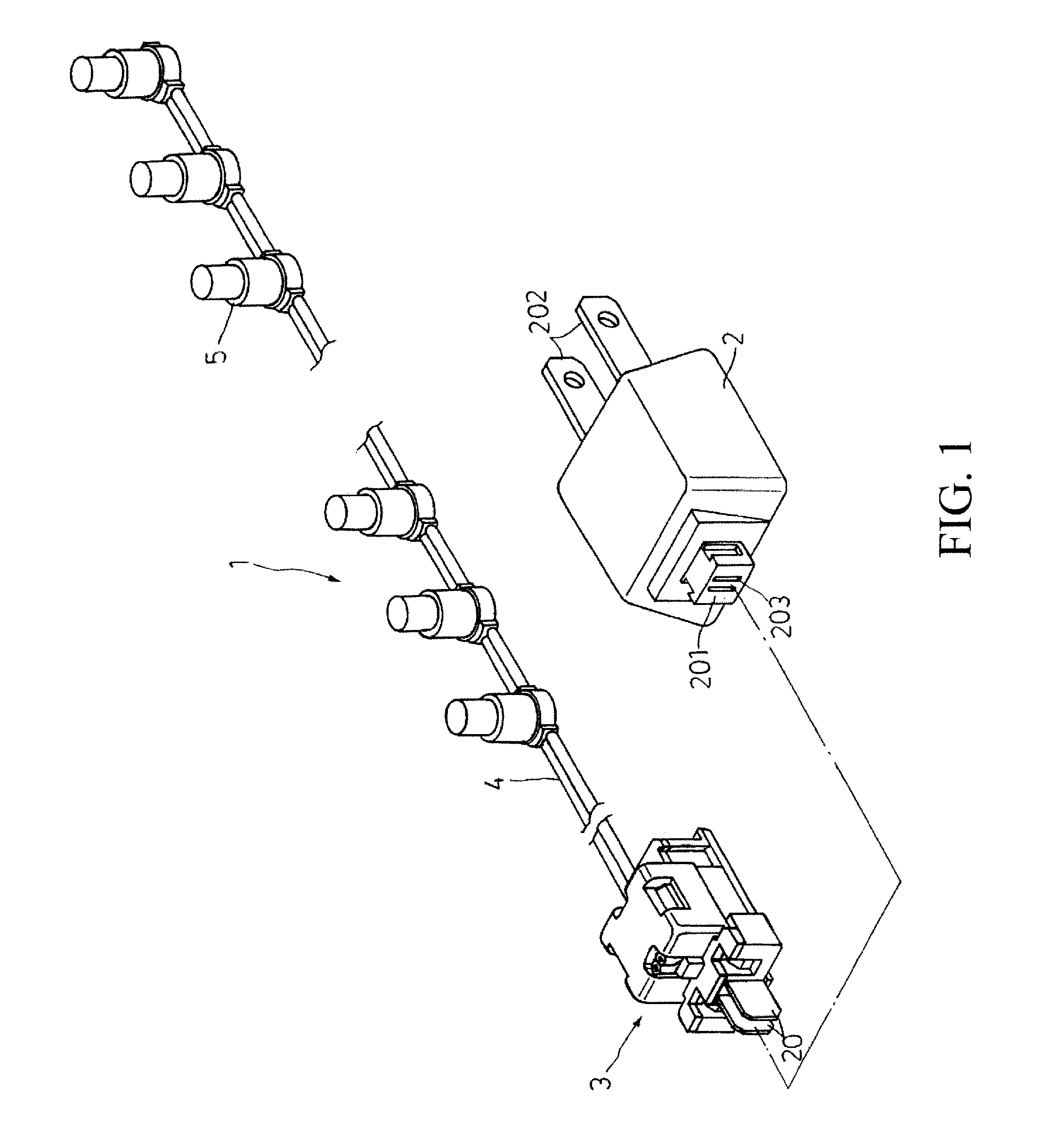
[0019]As shown in FIG. 1, a string light 1 where a connector 3 according to an embodiment of the present invention is installed further contains a cable 4, a number of LED lamps 5 configured along the cable 4, and a plug 2. The connector 3 is configured at an end of the cable 4 and has metallic plates 20 projecting from a front side of the connector 3. The plug 2 has prongs 202 extended from a front side of the plug 2 for plugging into a wall socket, and sockets 203 on a back side for receiving the ...


PUM


Abstract

The connector has a base with hooked side boards for joining a top cap. A partition board is placed between the side boards so as to form two slots for housing two metallic plates and two supporting pieces with slant top faces. The metallic plates have two upwardly extended conducting pins. Wires of exposed cores are placed on the supporting pieces. When the top cap is joined to the base, the wires are tightly locked by the top cap and the partition board while the conducting pins firmly contact with the cores. The connector can be quickly configured on a string of lamps and can be conveniently used to cascade multiple strings of lamps.

Description

BACKGROUND OF THE INVENTION[0001](a) Technical Field of the Invention[0002]The present invention is generally related to string lights, and more particular to a connector for cascading string lights.[0003](b) Description of the Prior Art[0004]To the inventor's knowledge, the manufacturing of conventional Christmas string lights involves a stage of welding or clamping wires of a string light to the prongs of a plug. This stage is usually conducted after the lamps of the string light are installed. In other words, a worker usually has to carry dangling strands of lamps, manually perform the welding or clamping, and then carry the string light to a next stage where a casing for the plug is put on. This process not only is troublesome, but also is time-consuming and laborious.SUMMARY OF THE INVENTION[0005]A novel connector is provided herein so as to obviate the shortcomings of the prior art. According to the present invention, the installation of the connector can be conducted along wi...

Claims


Application Information

Patent Timeline
IPC IPC(8): H01R25/00H01R4/24H01R27/02
CPCH01R27/02H01R4/5066H01R13/506H01R24/28F21S4/10
Inventor LIN, TE-HUI
Owner LIN TE HUI
Why Eureka
Try Eureka