Supercharge Your Innovation With Domain-Expert AI Agents!

Light-emitting diode lighting device having multiple driving stages and line/load regulation control

a technology of led lighting and driving stages, which is applied in the direction of electric lighting sources, electroluminescent light sources, and use of semiconductors. it can solve the problems that the overall line/load regulation of led lighting devices may not be able to meet desired values

Active Publication Date: 2016-04-12
IML HONG KONG LTD
View PDF10 Cites 6 Cited by
  • Summary
  • Abstract
  • Description
  • Claims
  • Application Information

AI Technical Summary

Benefits of technology

[0006]The present invention provides an LED lighting device having multiple driving stages. The LED lighting device includes a first luminescent device, a second luminescent device, a voltage detector, a first current controller, and a second current controller. The first luminescent device is driven by a rectified AC voltage for providing light according to first current. The second luminescent device is coupled in series to the first luminescent device and driven by the rectified AC voltage for providing light according to second current. The voltage detector is configured to monitor a variation in a peak level of the rectified AC voltage and generate a compensation voltage associated with the peak level of the rectified AC voltage. The first current controller is coupled in parallel with the first luminescent device and configured to regulate the first current so that the first current does not exceed a first current setting; and adjust the first current setting according to the compensation voltage. The second current controller is coupled in series to the second luminescent device and configured to regulate the second current so that the second current does not exceed a second current setting; and adjust the second current setting according to the compensation voltage.

Problems solved by technology

Since the current is regulated independently in each stage of a prior art LED lighting device according the voltage established across each stage, the overall line / load regulation of the LED lighting device may not be able meet desired values.

Method used


Image

  • Light-emitting diode lighting device having multiple driving stages and line/load regulation control
  • Light-emitting diode lighting device having multiple driving stages and line/load regulation control
  • Light-emitting diode lighting device having multiple driving stages and line/load regulation control

Examples


Embodiment Construction

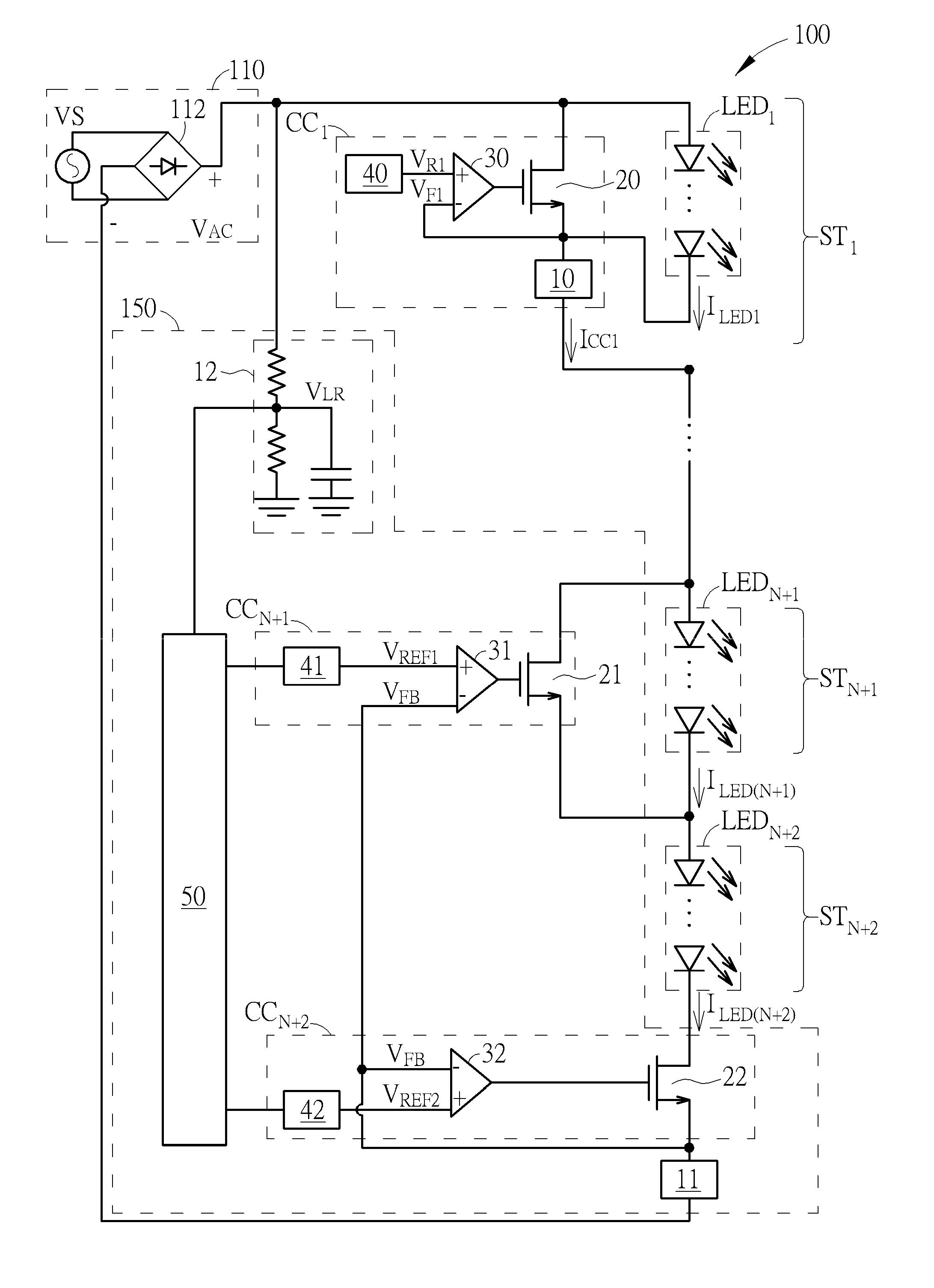
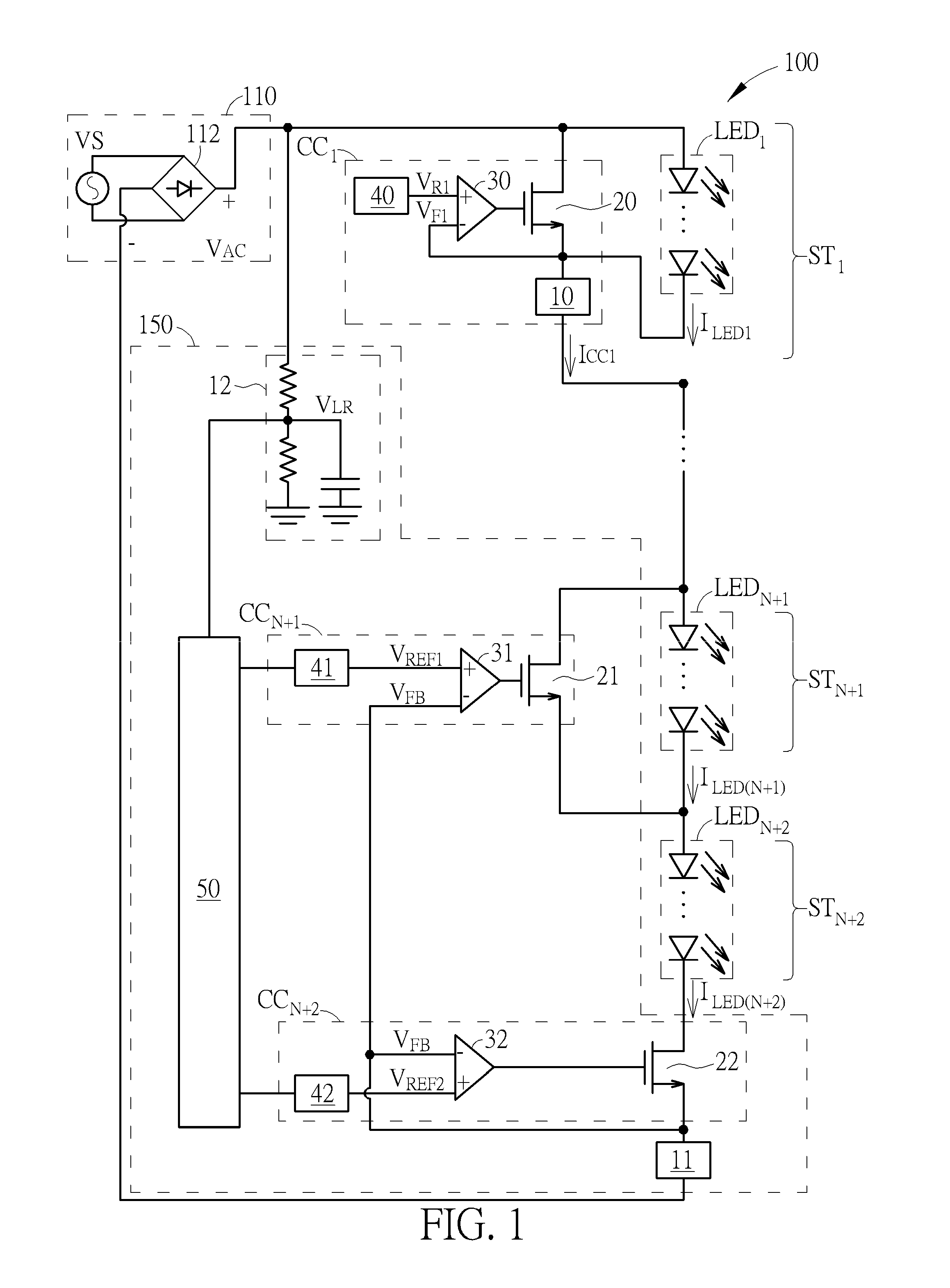
[0014]FIG. 1 is a diagram of an LED lighting device 100 according to an embodiment of the present invention. FIG. 2 is a diagram of an LED lighting device 200 according to another embodiment of the present invention. Each of the LED lighting device 100 and the LED lighting device 200 includes a power supply circuit 110 and (N+2) driving stages ST1˜STN+2 (N is a positive integer). The power supply circuit 110 is configured to receive an AC voltage VS having positive and negative periods and convert the output of the AC voltage VS in the negative period using a bridge rectifier 112, thereby providing a rectified AC voltage VAC, whose value varies periodically with time, for driving the LED lighting devices 100 and 200. In another embodiment, the power supply circuit 110 may receive any AC voltage VS, perform voltage conversion using an AC-AC converter, and rectify the converted AC voltage VS using the bridge rectifier 112, thereby providing the rectified AC voltage VAC whose value var...


PUM


Abstract

An LED lighting device includes multiple luminescent devices driven by a rectified AC voltage. The multiple luminescent devices are turned on flexibly in a multi-stage driving scheme using multiple current controllers. The current settings of the two driving stages with the highest current level and the second highest current level are adjusted according to the variation in the rectified AC voltage VAC or according to the variation in the duty cycle of the luminance device due to the variation in the rectified AC voltage. The present invention can improve the line / load regulation of the LED lighting device when the rectified AC voltage somehow fluctuates between its upper bound and lower bound.

Description

CROSS REFERENCE TO RELATED APPLICATIONS[0001]This application claims the benefit of U.S. provisional application No. 62 / 020,410 filed on 2014 Jul. 3.BACKGROUND OF THE INVENTION[0002]1. Field of the Invention[0003]The present invention is related to an LED lighting device having multiple driving stages, and more particularly, to an LED lighting device having multiple driving stages for improving operational voltage range and line / load regulation.[0004]2. Description of the Prior Art[0005]An LED lighting device directly driven by a rectified alternative-current (AC) voltage usually adopts a plurality of LEDs coupled in series in order to provide required luminance. In a conventional method for driving an LED lighting device, the LEDs may be light up in stages in order to increase the effective operational voltage range. Line regulation is the ability of an LED lighting device to exhibit little change in brightness or power as the rectified AC voltage changes. Load regulation is the co...

Claims


Application Information

Patent Timeline
Patent Type & Authority Patents(United States)
IPC IPC(8): H05B33/08H05B44/00
CPCH05B33/083H05B33/0812H05B45/48H05B45/395Y02B20/30
Inventor VIVIANI, ALBERTO GIOVANNIGODER, DIMITRYLU, CHUNCHENG, KAI-YUN
Owner IML HONG KONG LTD
Features
  • R&D
  • Intellectual Property
  • Life Sciences
  • Materials
  • Tech Scout
  • Unparalleled Data Quality
  • Higher Quality Content
  • 60% Fewer Hallucinations
Learn More