Electrode harness and method of taking biopotential measurements

a biopotential measurement and electrode harness technology, applied in the field of electrode harnesses, can solve the problems of increasing the risk of inaccurate measurements, more time and manpower required to operate and utilize, and the electrode harness is very sensitive to placement and contact with the subject's skin, so as to improve the use and performance of the electrode harness

Active Publication Date: 2016-05-03
ORBITAL RES
View PDF36 Cites 10 Cited by
  • Summary
  • Abstract
  • Description
  • Claims
  • Application Information

AI Technical Summary

Benefits of technology

[0009]The present invention relates to an electrode harness and more particularly to an electrode harness with various features, which enhance the use and performance of the electrode harness. The present invention further relates to a method of taking biopotential measurements.
[0011]The electrode harness of the present invention overcomes one or more of the significant drawbacks of other electrode systems. One of the features of various embodiments of the present invention includes a harness with lockable or non-releasable connectors, which allows for disposal or removal of the electrode harness and electrodes in one piece (application of harness and electrodes while maintaining the connection: i.e doesn't fall off or lose electrical connect once inserted. This prevents clutter and more importantly medical waste by reducing the possibility that the electrodes separate from the harness. Another feature of the electrode harness of the present invention is the use of an adjustable. connection point. More specifically, the electrode harness is provided with an electrode, which can be positioned in various locations over one of the arms of the harness allow for more accurate / reliable data capture. Preferably, the electrode operates on a track incorporated into the electrode harness over which the electrode can be moved and operated. Still another feature of the electrode harness of various embodiments of the present invention is partial or full shielding of the electrical pathways of the harness from electrical noise or more importantly from large defibrillator voltages. Still another feature of various embodiments of the electrode harness of the present invention is the ability to trim electrodes, electrical connections and / or arms of the electrode harness. Finally, another significant feature of the electrode harness of various embodiments of the present invention is the use of an electrode harness containing one or more dry electrodes.

Problems solved by technology

In addition, these electrodes are very sensitive to placement and contact with the subject's skin.
The more complicated these systems are the more time and manpower is required to operate and utilize them, and the greater the risk of inaccurate measurements.
The electrode harnesses, however, are simple and have not been very effective given most are difficult to use, and attempt to integrate existing electrode technology into their design.
None of the electrode harnesses developed use standard gel type electrodes, wherein once attached or connected, the electrodes cannot be released.
Therefore, once used with these connectable electrodes the existing electrode harnesses cannot be disposed of in one piece along with the harness since the electrode may become separated from the harness.
Another drawback is none of the electrode harnesses contain an adjustable connection point for the electrodes to allow for the harness to be adapted to either different sized subjects or different applications.
Still another drawback is none of the electrode harnesses electrically shield the electrodes from large defibrillator voltages.
Still yet another drawback is that none of the electrode harnesses contains trimable electrodes or electrical connections so the electrode harness can be personally modified for a particular subject or application.

Method used


Image

  • Electrode harness and method of taking biopotential measurements
  • Electrode harness and method of taking biopotential measurements
  • Electrode harness and method of taking biopotential measurements

Examples


Embodiment Construction

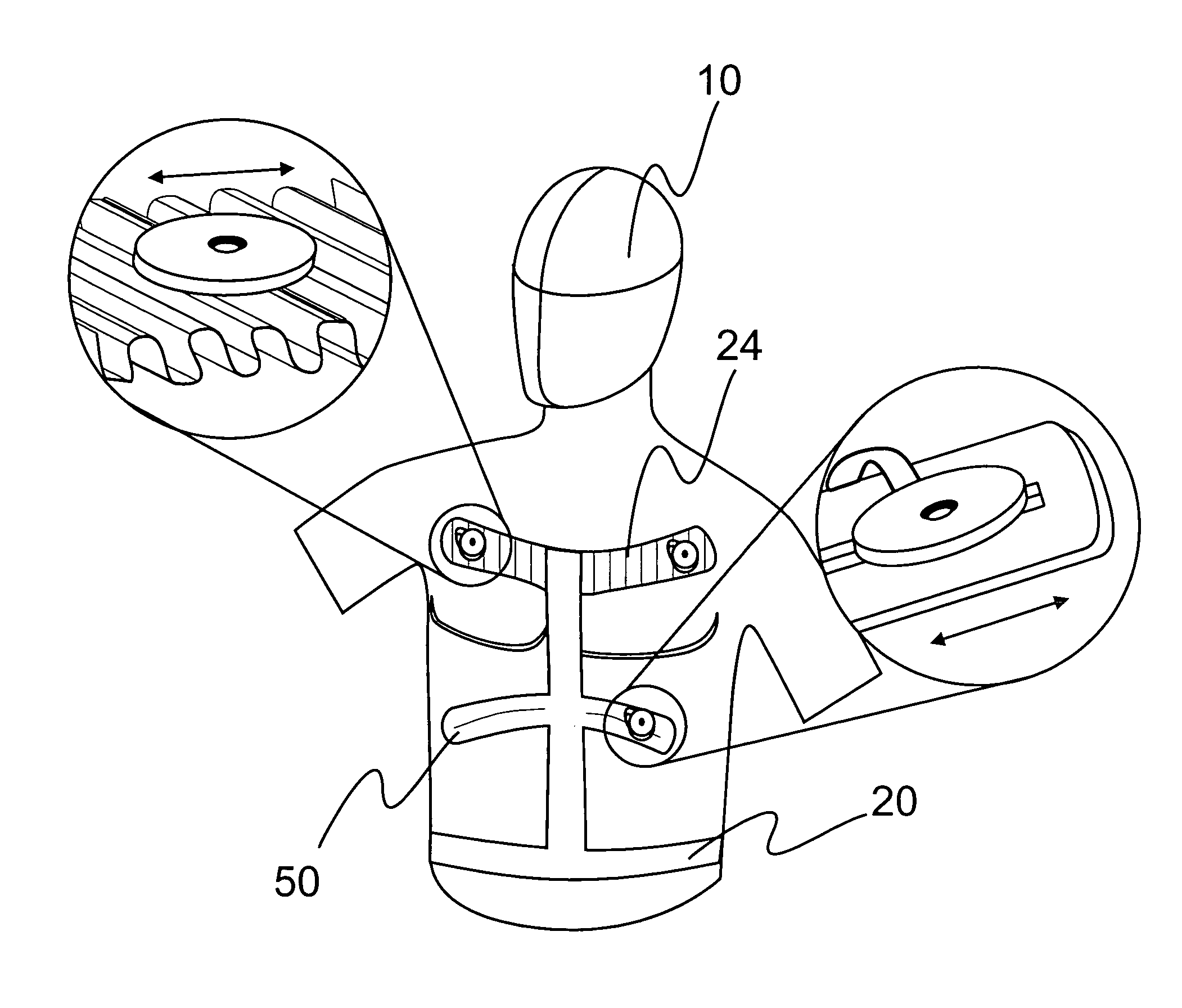
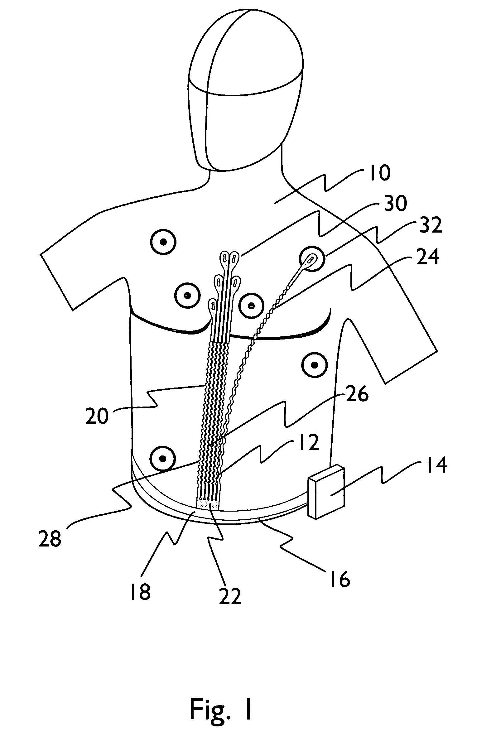
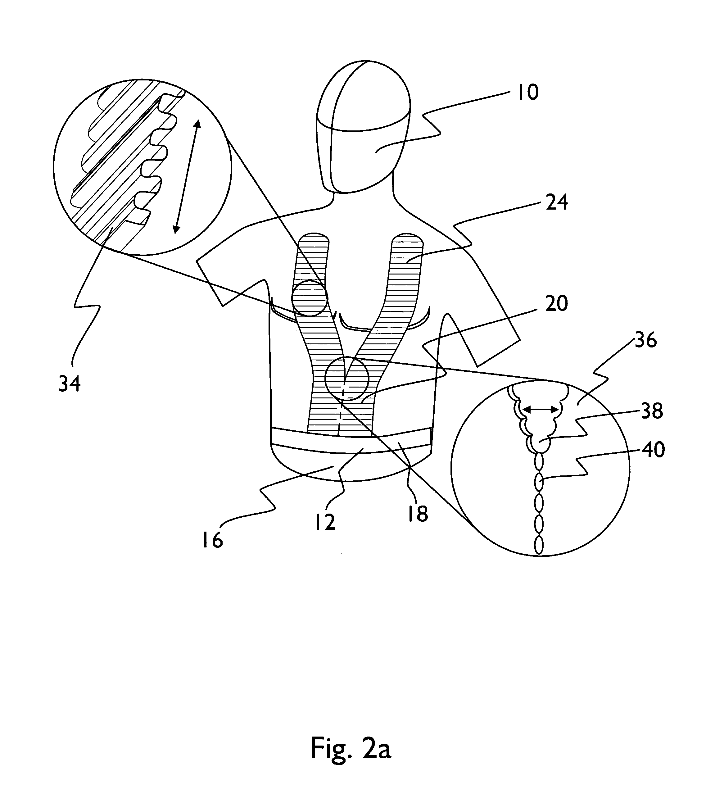
[0033]The present invention relates to an electrode harness and more particularly to an electrode harness with various features, which enhance the use and performance of the electrode harness. The present invention further relates to a method of taking a physiological or preferably a biopotential measurement.

[0034]The various embodiments of the electrode harness and methods of the present invention allow for use with most applications where biopotential or physiological measurements are taken. The electrode harness of the present invention is preferably used for sensing or detecting a physiological or biopotential signal from a subject. The subject from which a physiological signal is measured being a human or other form of animal. The electrode harness can be used in a variety of applications including but not limited to electrocardiography (ECG), electroencephalography (EEG), electrical impedance tomography (EIT), electromyography (EMG), electro-oculography (EOG) and Bio-electrica...


PUM


Abstract

The present invention relates to an electrode harness and more particularly to an electrode harness with various features, which enhance the use and performance of the electrode harness. The present invention further relates to a method of taking biopotential measurements. The electrode harness and methods of the present invention allow for use with most applications where biopotential measurements are taken. The electrode harness can be used in ECG (or EKG), EEG, EMG, and other such biopotential measurement applications. Because of the versatility of various embodiments of the present invention, preferably the electrode harness can be adjusted for different applications or for application to various sized and shaped subjects. The electrode harness is further preferably part of a system, which includes either wireless or tethered bridges between the electrode harness and a monitor, and preferably includes various forms of processors for analyzing the biopotential signal.

Description

[0001]The U.S. Government has a paid-up license in this invention and the right in limited circumstances to require the patent owner to license others on reasonable terms provided for by the terms of contract number DMI-0216284 awarded by the National Science Foundation.BACKGROUND OF THE INVENTION[0002]1. Field of the Invention[0003]The present invention relates to an electrode harness and more particularly to an electrode harness with various features, which enhance the use and performance of the electrode harness. The present invention further relates to a method of taking biopotential measurements.[0004]2. Technical Background[0005]Medical diagnostics include many tests that obtain biopotential measurements from the surface or just under the surface of the skin of a subject. These tests vary widely, ranging from the electro-cardiogram (EKG) that measures electric impulses generated by the heart, to the electroencephalogram (EEG) which measures electric impulses generated by the b...

Claims


Application Information

Patent Timeline
Patent Type & Authority Patents(United States)
IPC IPC(8): A61B5/0408
CPCA61B5/04085A61B5/6831A61B5/0408A61B5/0476A61B5/0488A61B5/0496A61B2562/227A61B5/282A61B5/369A61B5/389A61B5/398A61B5/0006A61B5/053A61B5/684A61B5/7271A61B2562/182A61B5/25
Inventor KRYZPOW, DAVIDELLIOTT, JAMESROOD, AARONLISY, FREDERICK J.
Owner ORBITAL RES
Why Eureka
Try Eureka