Sheet manufacturing apparatus

a technology of manufacturing apparatus and sheets, applied in the field of sheets manufacturing apparatus, can solve the problems of less readily corrected, increased size of the apparatus, and skewing of the apparatus, and achieve the effect of increasing the tensile strength of the web itsel

Active Publication Date: 2016-05-03
SEIKO EPSON CORP
View PDF15 Cites 5 Cited by
  • Summary
  • Abstract
  • Description
  • Claims
  • Application Information

AI Technical Summary

Benefits of technology

[0009]According to the configuration of such description, the formed web is first cut in a direction intersecting with the transfer direction of the web. For this reason, the occurrence of skewing (such as meandering or bending in the transferring of the web) of the web being transferred is curbed. A web that is not cut in a direction intersecting with the transfer direction will be continuous, experiences skewing, and even still is less readily corrected. Effectuating a state of having been cut and made into the form of a sheet facilitates correction of skewing. Then, after having been cut, the web is heated. Because the web is heated in a state where the orientation of the web has been aligned, it is possible to heat evenly. Because the web is heated after having been cut, the web can be prevented from generating cutting powder or the like. The web is also heated by a heating unit in the form of a roller. This makes it possible to continuously manufacture the sheet and to reduce the apparatus configuration in size compared to a case of heating with a planar pressing machine. A case where a planar pressing apparatus is used would necessitate a buffer unit for temporarily giving slack to the web being transferred when the pressing is being performed.
[0011]According to the configuration of such description, it becomes possible to cut along the transfer direction of the web in a state where skewing has been reduced. This makes it possible to accurately cut the web to the desired dimensions.
[0013]According to the configuration of such description, the web is cooled after having been heated by the heating unit. Because of this cooling, the web in a softened state following the heating is cooled by the cooling and the strength is increased. The cutting is performed in a state where the strength of the web has been ensured. As such, the web can be accurately cut to the desired dimensions. Here, the “cooling unit” is understood to encompass a unit that does not heat. That is to say, the cooling unit is provided with a function where the temperature is lower than that of the web that has been heated by the heating unit.
[0015]According to the configuration of such description, the strength of the resulting sheet can be upheld and a high-quality sheet can be manufactured.
[0017]According to the configuration of such description, the web is heated in advance at an earlier stage than the heating unit. This increases the tensile strength of the web itself. Then, after the preheating, the web is cut in the direction intersecting with the transfer direction of the web. As such, any breaking of the web at the time of cutting can be curbed.

Problems solved by technology

For this reason, a problem emerges in that the apparatus configuration is increased in size.
A web that is not cut in a direction intersecting with the transfer direction will be continuous, experiences skewing, and even still is less readily corrected.

Method used


Image

  • Sheet manufacturing apparatus
  • Sheet manufacturing apparatus
  • Sheet manufacturing apparatus

Examples


modification example 1

[0049]The embodiment described above is provided with the preheating unit 140 having the second rollers 141 for heating the web W at a lower temperature or lower load than the heating units 120, between the web forming unit 70 and the first cutting unit 110; however, there is no limitation to being of this configuration. For example, the configuration may be one where the preheating unit 140 has been omitted. Even still, it would remain possible to have effects similar to what is described above and also to reduce in size the overall configuration of the sheet manufacturing apparatus 1.

modification example 2

[0050]The embodiment described above is configured so that there are two heating units 120a, 120b arranged as the heating unit 120, but there is no limitation to being of this configuration. For example, depending on the thickness, material or other attributes of the web W being manufactured (the sheet Pr), the configuration may be one where only one heating unit 120 is arranged, or the configuration may be one where three or more heating units 120 are arranged, and settings may be made as appropriate. So doing makes it possible to manufacture (form) the sheet Pr (web W) efficiently.

modification example 3

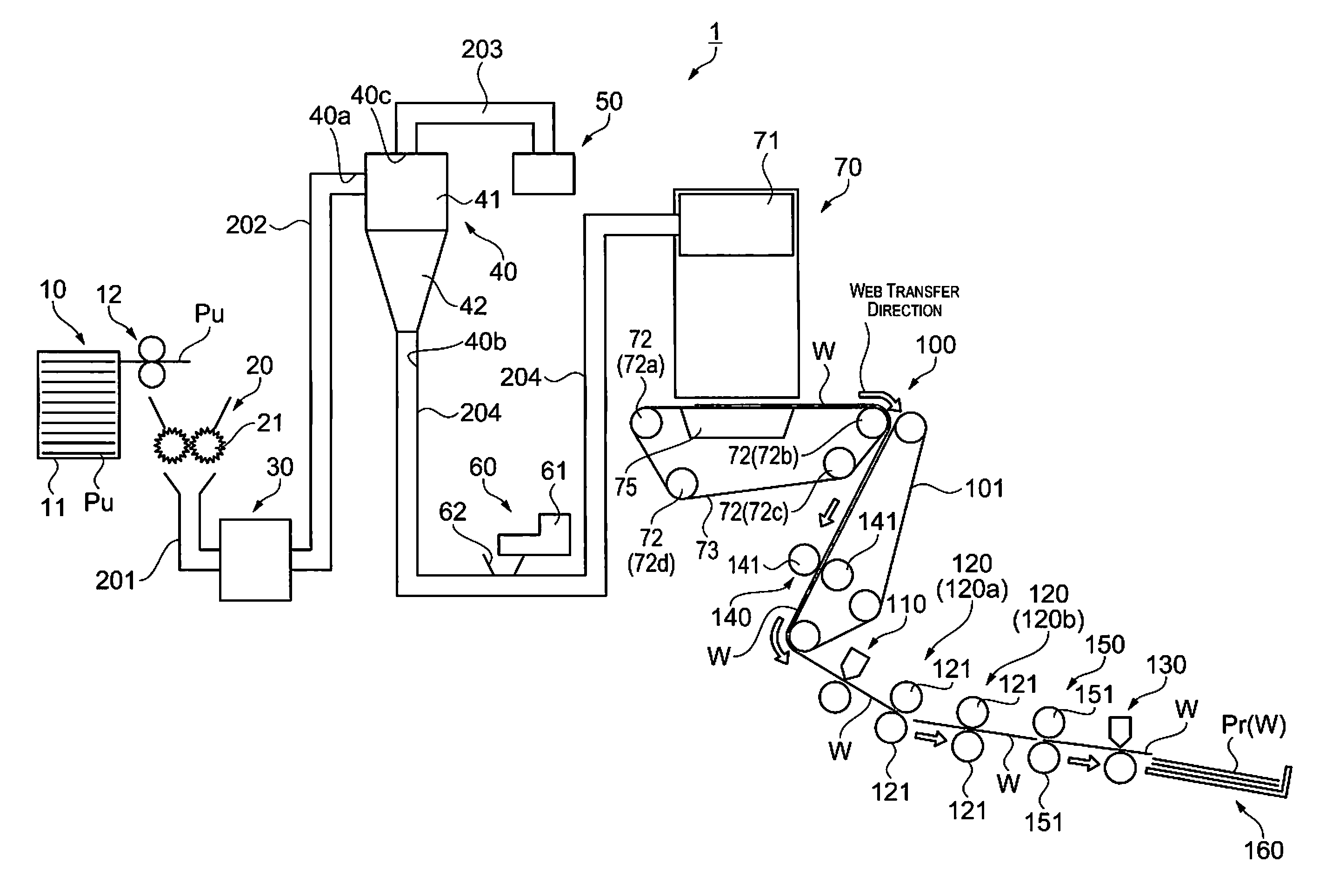
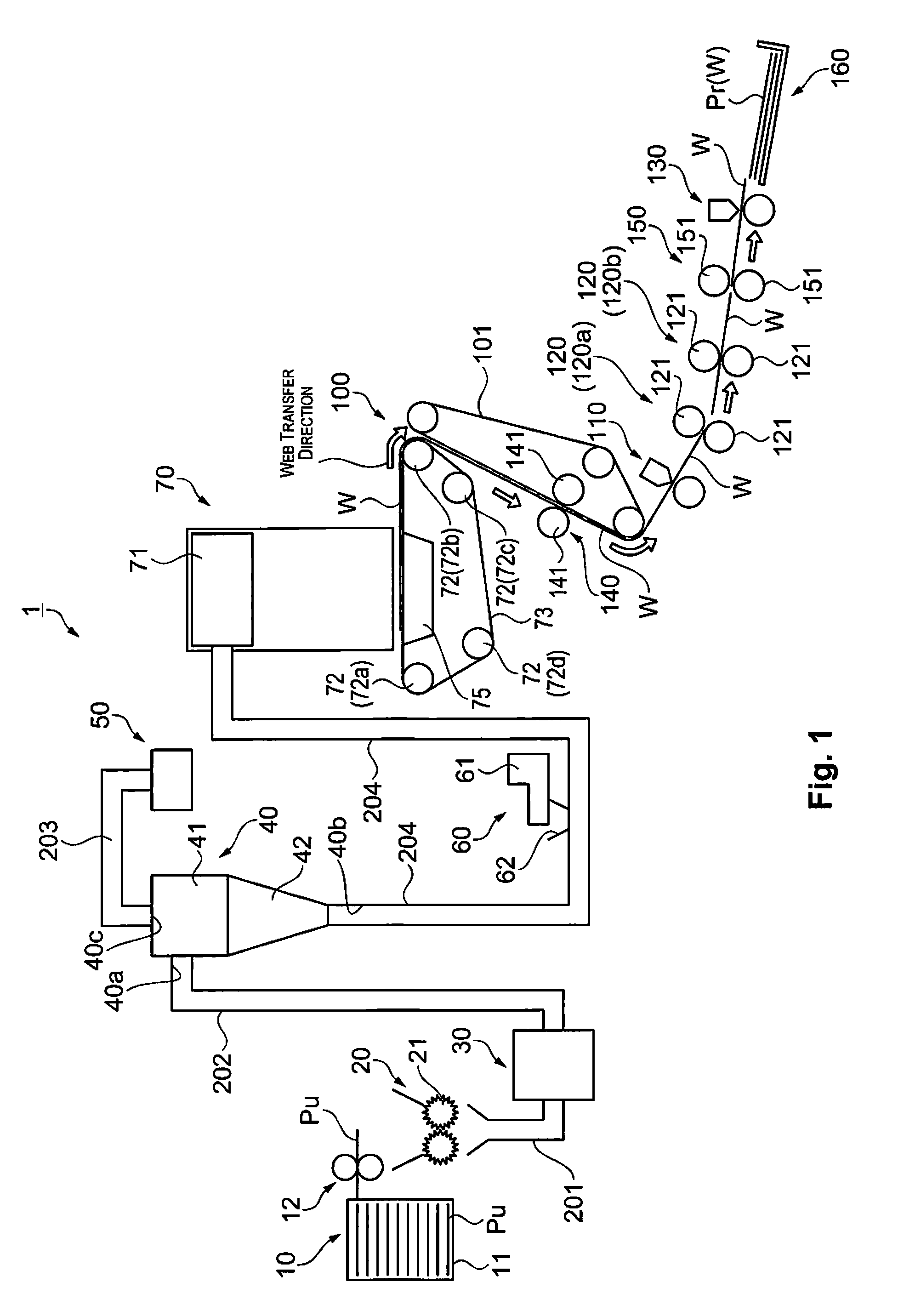
[0051]FIG. 3 is a drawing illustrating the minimum constituent elements in the present application. The sheet manufacturing apparatus 1 is provided with the web forming unit 70, the transferring unit 100, the first cutting unit 110, and the heating unit 120. In a case where fibers and resin that have been mixed together in advance is used as the stock material, then there is no need for the constituent elements more upstream in the direction of flow than the web forming unit 70, such as the supplying unit 10, the crushing unit 20, the defibrating unit 30, the classifier unit 40, or the additive agent feeding unit 60 (see FIG. 1). Also, the temperature drops naturally even without the cooling rollers 151 (the cooling unit 150 (see FIG. 1)). The second cutting unit 130 (see FIG. 1) is also unnecessary, provided that a cut is made after the sheet has been taken out from the sheet manufacturing apparatus 1. Each of the constituent elements understood to be unneeded on the basis of the c...


PUM

PropertyMeasurementUnit
temperatureaaaaaaaaaa
lengthaaaaaaaaaa
sizeaaaaaaaaaa

Abstract

A sheet manufacturing apparatus includes a web forming unit configured to form a web that includes fibers and a resin, a transferring unit configured to transfer the web that has been formed, a first cutting unit configured to cut the web in a direction intersecting with a transfer direction of the web being transferred, and a heating unit having a first roller configured to heat the web that has been cut.

Description

CROSS-REFERENCE TO RELATED APPLICATIONS[0001]This application claims priority to Japanese Patent Application No. 2013-207965 filed on Oct. 3, 2013. The entire disclosure of Japanese Patent Application No. 2013-207965 is hereby incorporated herein by reference.BACKGROUND[0002]1. Technical Field[0003]The present invention relates to a sheet manufacturing apparatus.[0004]2. Related Art[0005]Conventionally known are recycled pulp molding and drying apparatuses (for example, see Japanese laid-open patent publication No. 2009-299217) provided inter alia with a mesh belt conveyor for transferring a web (a “pulp sheet” in Japanese laid-open patent publication No. 2009-299217), a cutter for cutting the transferred web to a predetermined length, and heating and pressing machine that is arranged more downstream than the cutter in the direction of transfer of the web and heats and dries the cut web.[0006]However, the heating and pressing machine of the recycled pulp molding and drying apparatus...

Claims


Application Information

Patent Timeline
Patent Type & Authority Patents(United States)
IPC IPC(8): D21F7/00B65H29/14B65H29/12D21F9/00
CPCD21F9/00B65H29/125B65H29/14B65H2301/121B65H2301/5143B65H2301/5144B65H2801/84
Inventor FUJITA, SHIGEOGOMI, KATSUHITOSEKI, SHUNICHI
Owner SEIKO EPSON CORP
Why Eureka
Try Eureka