
Electronic apparatus

a technology of electromechanical devices and claws, applied in the direction of electromechanical process devices, instruments, support structure mounting, etc., can solve the problems of age-related deterioration of biasing means, inability of biasing means to apply a stable biasing force to the claw members, etc., to reduce age-related deterioration of elastic deformation members and stably retain panels

Active Publication Date: 2016-05-03
BROTHER KOGYO KK
View PDF12 Cites 5 Cited by
  • Summary
  • Abstract
  • Description
  • Claims
  • Application Information

AI Technical Summary

Benefits of technology

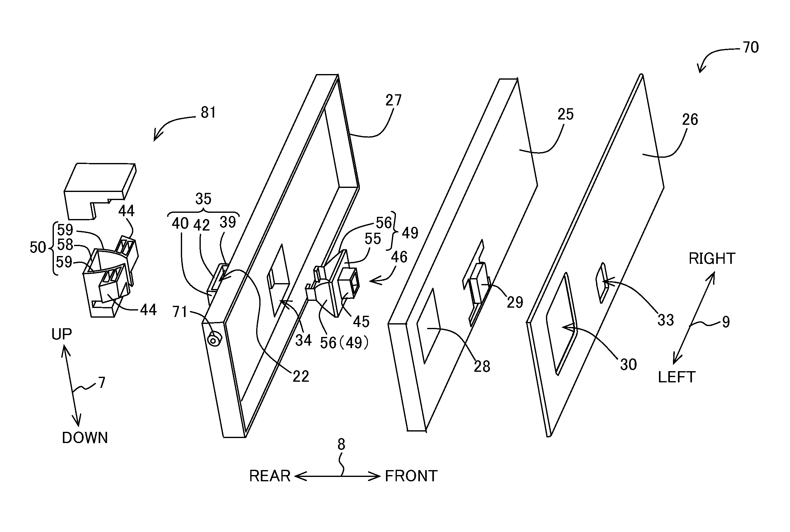
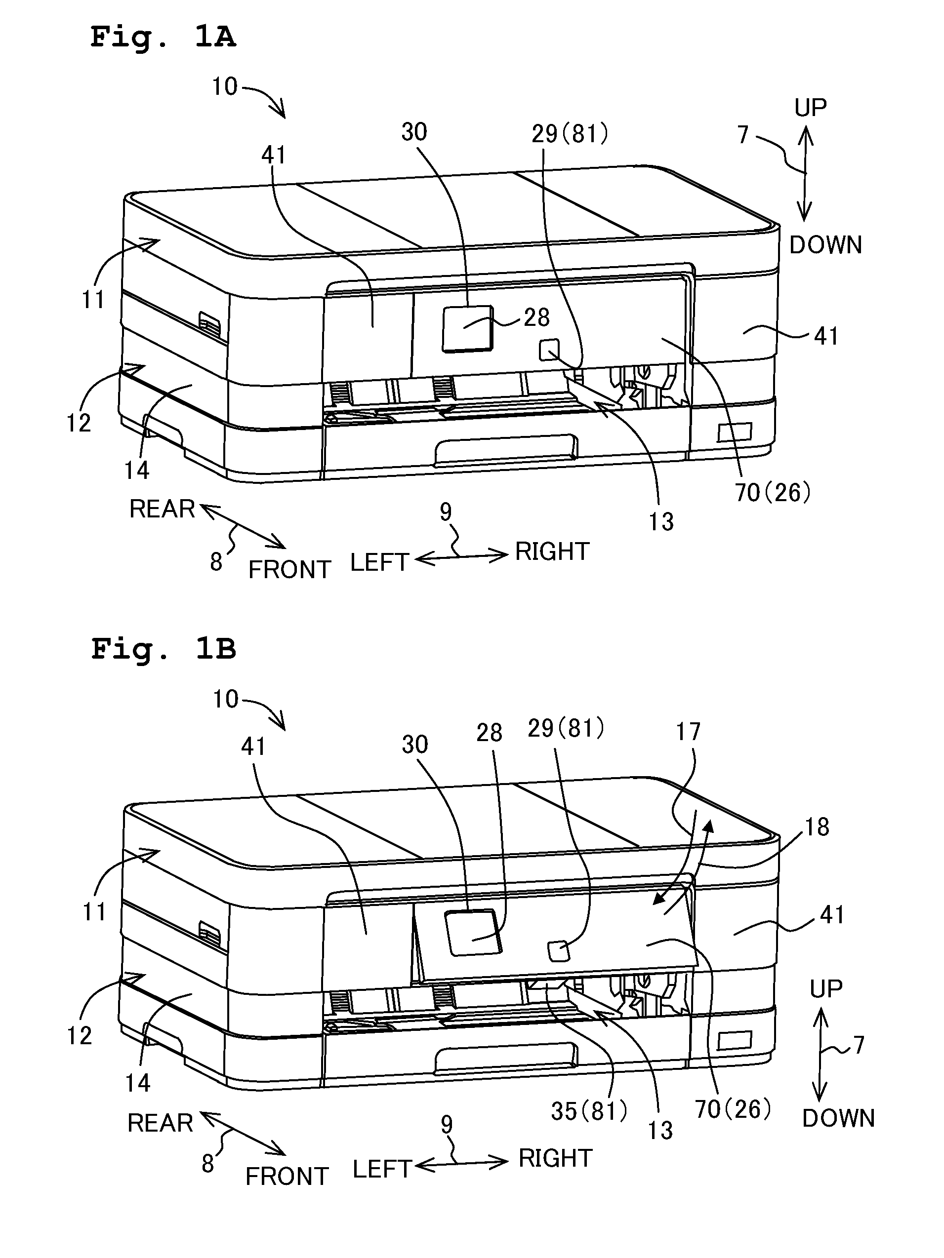
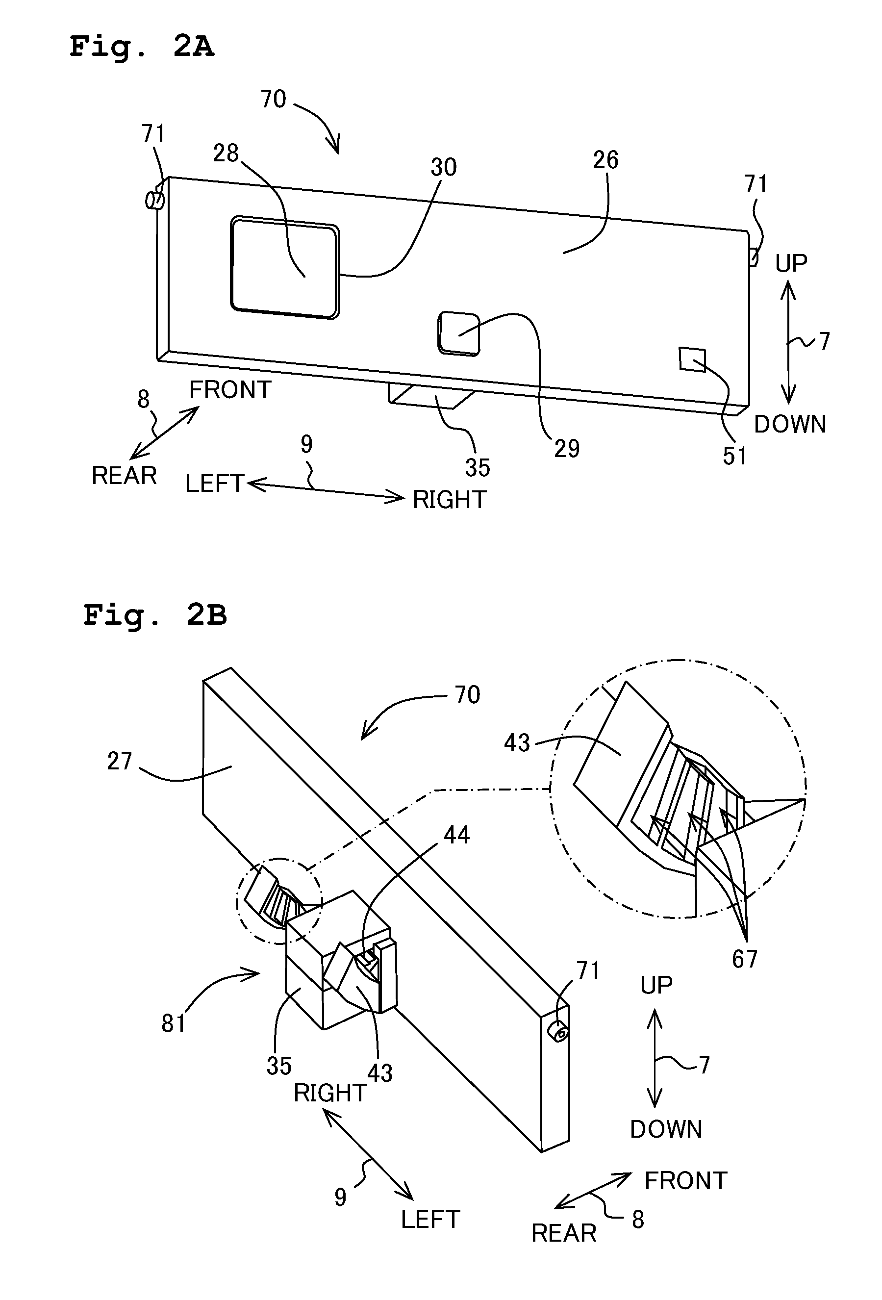
[0012]According to this configuration, the elastic deformation member elastically deforms only when the panel is rotated by the retained member being separated from the retaining member, but does not elastically deform when the panel is retained at the predetermined rotation angle by the retained member being retained by the retaining member. The time of retaining the panel at the predetermined rotation angle is overwhelmingly longer than the time of rotating the panel. Hence, according to this configuration, it is possible to reduce age-related deterioration of the elastic deformation member due to longtime elastic deformation. As a result, it is possible to stably retain the panel in a predetermined posture.

Problems solved by technology

That is, because the biasing means constantly biases the claw member, age-related deterioration is liable to occur in the biasing means.
As a result, the biasing means becomes incapable of applying a stable biasing force to the claw member to engage with the recess.

Method used


Image

  • Electronic apparatus
  • Electronic apparatus
  • Electronic apparatus

Examples


first modification

[First Modification]

[0099]In the above embodiment, the elastic deformation member 46 is configured to undergo elastic deformation in a direction along the rotation shaft 71 of the panel 70. However, the elastic deformation member 46 may alternatively undergo elastic deformation in a direction orthogonal to the rotation shaft 71 of the panel 70 and along the surface of the panel 70. Further, in explaining the configuration and operation of an electronic apparatus in the following first modification, with respect to the same parts as in the above embodiment, the explanation will be simplified or omitted.

[0100]As shown in FIG. 8, in the first modification, only one retaining member 43 is provided below the panel 70. Further, the recesses 67 of the retaining member 43 dent downward from the upper surface of the retaining member 43.

[0101]As shown in FIGS. 9A to 9D, only one retained member 44 is provided. Further, the elastic deformation member 46 is arranged to be rotated 90 degrees wit...

second modification

[Second Modification]

[0110]In the aforementioned embodiment, the elastic deformation member 46 is constructed of two members, i.e., the first flexible member 49 and the second flexible member 50. However, the elastic deformation member 46 may also be constructed of one member. In such case, for example, the elastic deformation member 46 may be constructed of the first flexible member 49 alone, and the retained members 44 may be fitted on the fore-end portions of the pair of the elastic plates 56 of the first flexible member 49. By configuration in this manner, if the pair of elastic plates 56 contact with the inflection apical ends 47 of the contact member 35 so as to bend such that the interval between each other becomes shorter in the left-right direction 9, then the retained members 44 are separated from the retaining members 43.

third modification

[Third Modification]

[0111]In the aforementioned embodiment, the elastic deformation member 46 is arranged to be movable relative to the panel 70, and the contact member 35 is arranged to be fixed on the panel 70. However, the elastic deformation member 46 and contact member 35 are not limited to such kind of arrangement. For example, the elastic deformation member 46 may be arranged to be fixed on the panel 70, whereas the contact member 35 may be arranged to be movable relative to the panel 70. Then, the elastic deformation member 46 may undergo elastic deformation by being pressed by the contact member 35 which is caused to move by manipulating the operating member 45.


PUM


Abstract

An electronic apparatus includes: a panel having at least one of an input section and a display section; a main body configured to retain the panel rotatably; and a retention mechanism configured to retain the panel at a predetermined rotation angle. The retention mechanism includes: a retaining member provided in the main body; a retained member provided on the panel and configured to be retained by the retaining member; an elastic deformation member configured to be connected to the retained member and changeable between a first state in which the elastic deformation member is not elastically deformed and a second state in which the elastic deformation member is elastically deformed; a contact member configured to contact with the elastic deformation member and change the state of the elastic deformation member; and an operating member configured to receive an operation for making the elastic deformation member contact with the contact member.

Description

CROSS REFERENCE TO RELATED APPLICATION[0001]The present application claims priority from Japanese Patent Application No. 2012-218712, filed on Sep. 28, 2012, the disclosure of which is incorporated herein by reference in its entirety.BACKGROUND OF THE INVENTION[0002]1. Field of the Invention[0003]The present invention relates to an electronic apparatus including a panel which is rotatably provided in its main body, and a retention mechanism which retains the panel at a predetermined rotation angle.[0004]2. Description of the Related Art[0005]Conventionally, as electronic apparatuses having a panel, there have been printers, scanners, copy machines, facsimile machines, and the like.[0006]It is assumable that the panel is operated either from the upper side of the apparatus or from the front side of the apparatus. Therefore, if the panel is directed to the apparatus upper side, the operability from the front side becomes bad. On the other hand, if the panel is directed to the apparatu...

Claims


Application Information

Patent Timeline
Patent Type & Authority Patents(United States)
IPC IPC(8): G03G15/00H05K7/14
CPCH05K7/14G03G15/5016
Inventor NAMBA, MAMORU
Owner BROTHER KOGYO KK
Learn More