Electronic apparatus
a technology of electromechanical devices and claws, applied in the field of electromechanical devices, can solve the problems of age-related deterioration of biasing means, inability of biasing means to apply a stable biasing force to the claw members, etc., and achieve the effect of reducing age-related deterioration of elastic deformation members and stably retaining panels
- Summary
- Abstract
- Description
- Claims
- Application Information
AI Technical Summary
Benefits of technology
Problems solved by technology
Method used
Image
Examples
first modification
[First Modification]
[0099]In the above embodiment, the elastic deformation member 46 is configured to undergo elastic deformation in a direction along the rotation shaft 71 of the panel 70. However, the elastic deformation member 46 may alternatively undergo elastic deformation in a direction orthogonal to the rotation shaft 71 of the panel 70 and along the surface of the panel 70. Further, in explaining the configuration and operation of an electronic apparatus in the following first modification, with respect to the same parts as in the above embodiment, the explanation will be simplified or omitted.
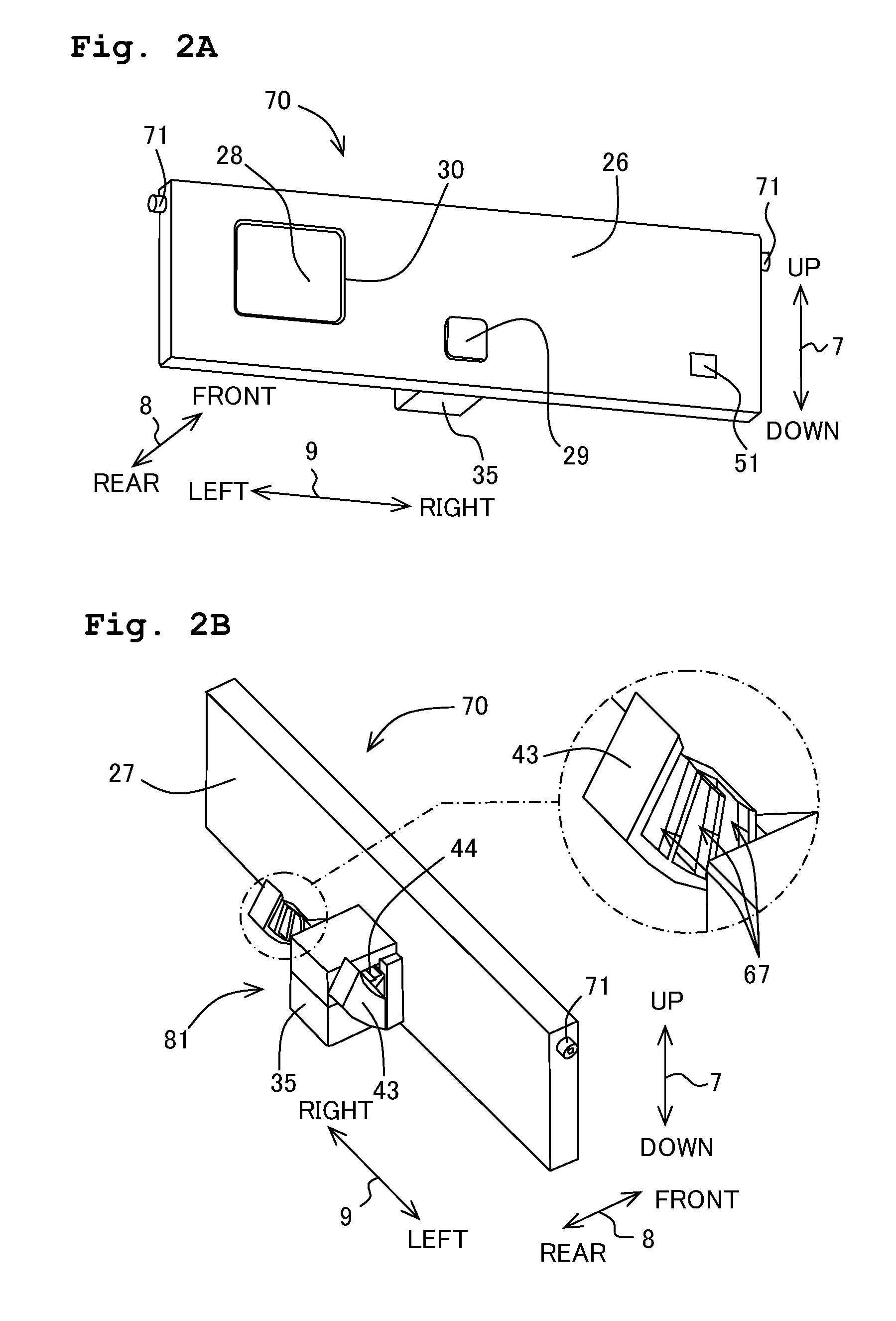
[0100]As shown in FIG. 8, in the first modification, only one retaining member 43 is provided below the panel 70. Further, the recesses 67 of the retaining member 43 dent downward from the upper surface of the retaining member 43.
[0101]As shown in FIGS. 9A to 9D, only one retained member 44 is provided. Further, the elastic deformation member 46 is arranged to be rotated 90 degrees wit...
second modification
[Second Modification]
[0110]In the aforementioned embodiment, the elastic deformation member 46 is constructed of two members, i.e., the first flexible member 49 and the second flexible member 50. However, the elastic deformation member 46 may also be constructed of one member. In such case, for example, the elastic deformation member 46 may be constructed of the first flexible member 49 alone, and the retained members 44 may be fitted on the fore-end portions of the pair of the elastic plates 56 of the first flexible member 49. By configuration in this manner, if the pair of elastic plates 56 contact with the inflection apical ends 47 of the contact member 35 so as to bend such that the interval between each other becomes shorter in the left-right direction 9, then the retained members 44 are separated from the retaining members 43.
third modification
[Third Modification]
[0111]In the aforementioned embodiment, the elastic deformation member 46 is arranged to be movable relative to the panel 70, and the contact member 35 is arranged to be fixed on the panel 70. However, the elastic deformation member 46 and contact member 35 are not limited to such kind of arrangement. For example, the elastic deformation member 46 may be arranged to be fixed on the panel 70, whereas the contact member 35 may be arranged to be movable relative to the panel 70. Then, the elastic deformation member 46 may undergo elastic deformation by being pressed by the contact member 35 which is caused to move by manipulating the operating member 45.
PUM
 Abstract
Description
Claims
Application Information
 - R&D
- Intellectual Property
- Life Sciences
- Materials
- Tech Scout
- Unparalleled Data Quality
- Higher Quality Content
- 60% Fewer Hallucinations
Browse by: Latest US Patents, China's latest patents, Technical Efficacy Thesaurus, Application Domain, Technology Topic, Popular Technical Reports.
© 2025 PatSnap. All rights reserved.Legal|Privacy policy|Modern Slavery Act Transparency Statement|Sitemap|About US| Contact US: help@patsnap.com


