Voltage regulation subsystem

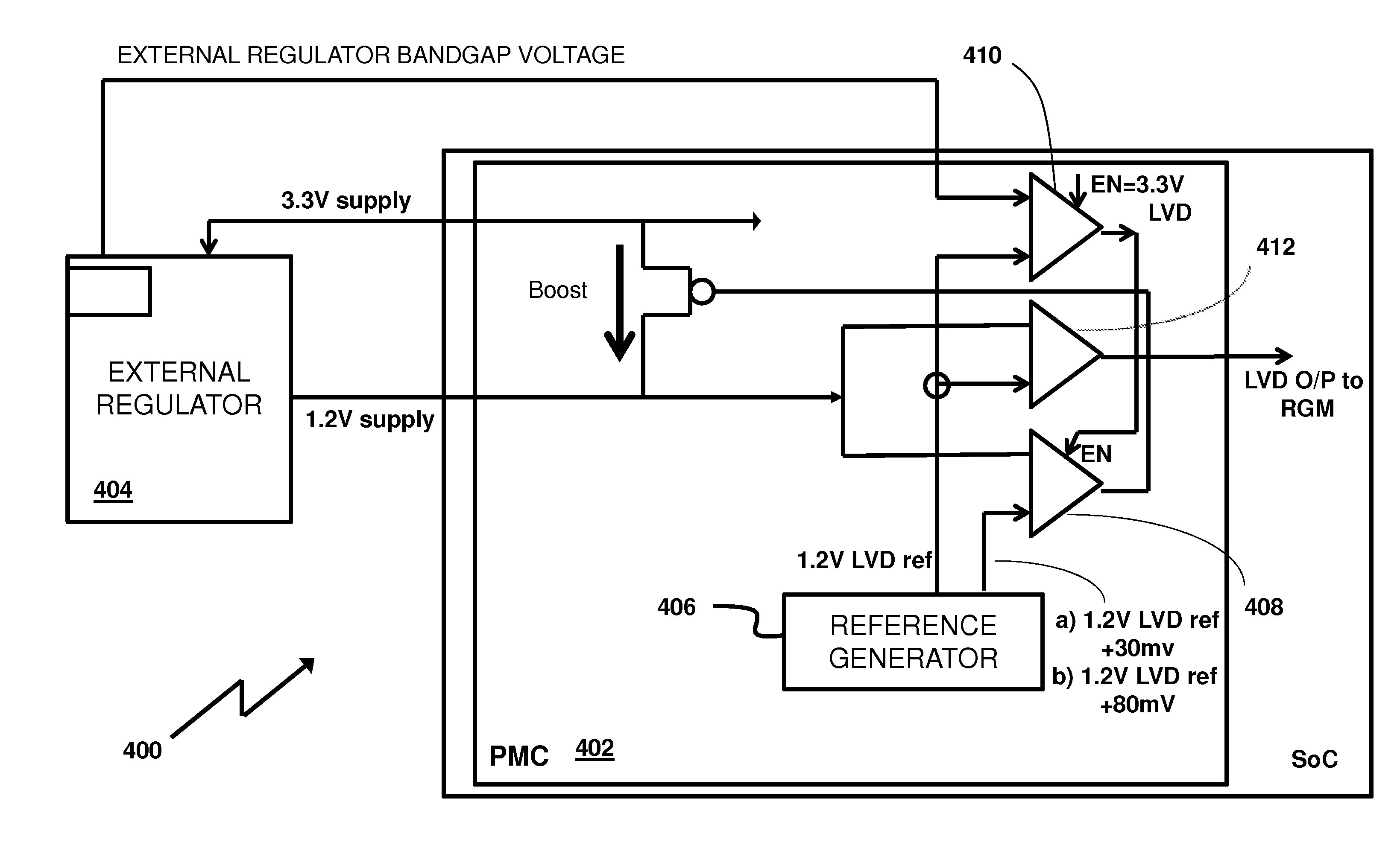
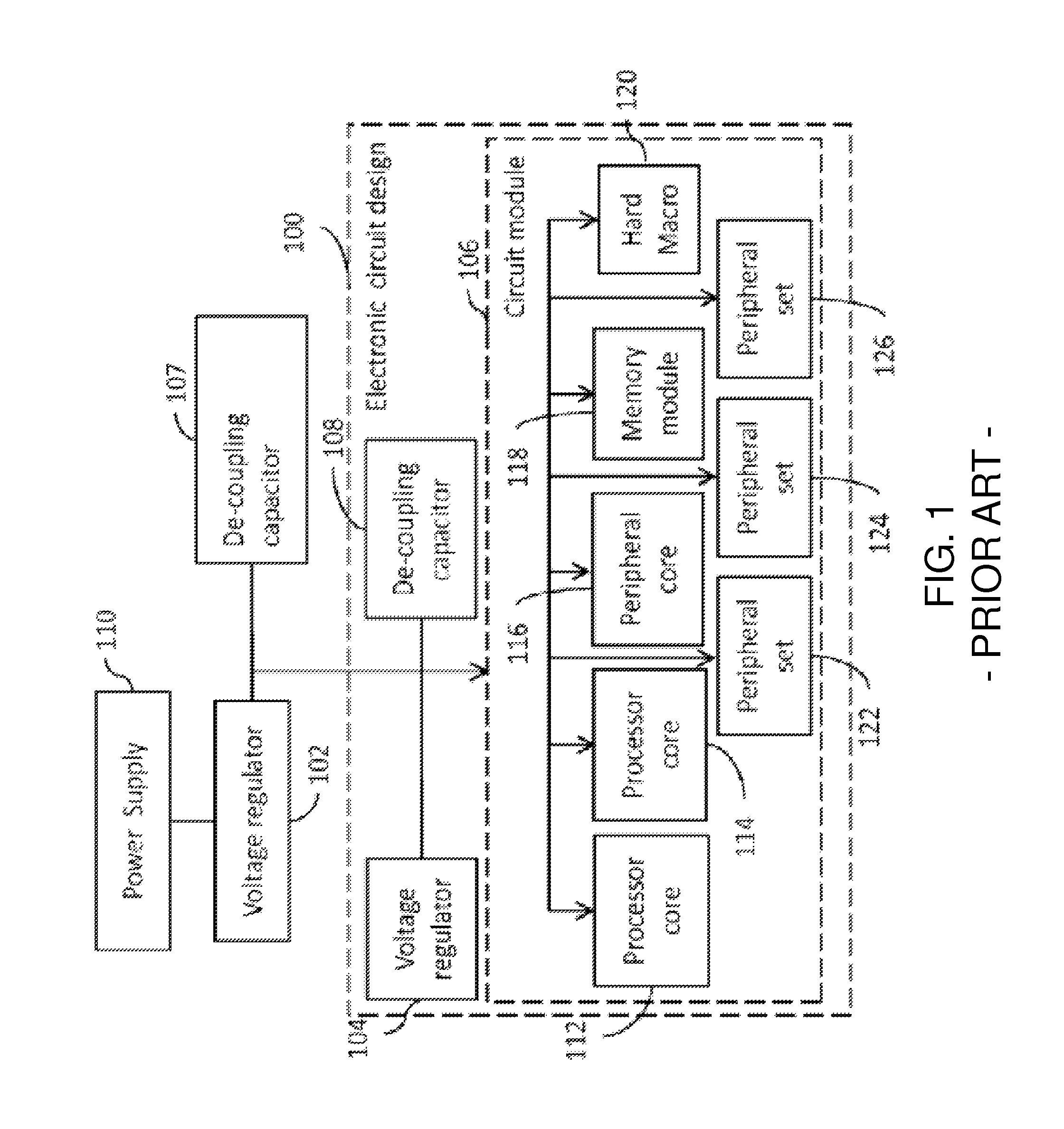
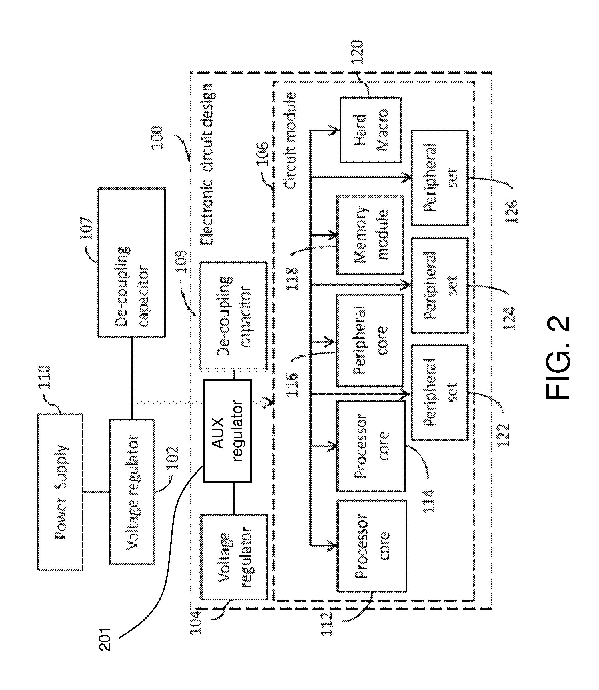
a voltage regulation and subsystem technology, applied in the direction of electric variable regulation, process and machine control, instruments, etc., can solve the problems of lvd comparators, limited die area, and ever greater current demand and thermal stresses

Active Publication Date: 2016-05-24
NXP USA INC
View PDF61 Cites 5 Cited by
  • Summary
  • Abstract
  • Description
  • Claims
  • Application Information

AI Technical Summary

Problems solved by technology

As microprocessor circuitry develops to operate at higher frequencies and as the density of transistors on integrated circuits increases, the vastly increased number of transitions in transistor state in the limited area of each integrated circuit leads to ever greater current demand and thermal stresses.
Other performance constraints include efficiency (i.e., minimization of losses) and power density.
For example, when the current requirement is very high and the die area is limited.
In some cases, this requires the software or a user to overdrive the supply voltage at power up and reset.
In fact, trims are applied only after the system has determined that the supply voltage exceeds the untrimmed levels of the bandgap and that LVD comparators have tripped.
If the PMC units are disabled, external off-chip LVD monitors are required instead, which adds complexity and cost.
If, on the other hand, core voltage is increased to counter LVD untrimmed range (while the internal LVD monitoring unit of the SoC is enabled), it leads to higher power consumption in operating mode.
Untrimmed LVD levels cannot be reduced as this may lead to a number of challenges arising from low supply voltage.
If the untrimmed LVD levels were reduced, allowing the supply voltage to drop to a reduced level without triggering the LVD comparator, this would at some point increase power consumption.
Furthermore, if the supply voltage were to go below a certain Vmin, where Vmin is the voltage at which timing has been met for the entire digital logic, timing related setup and hold violation would ensue leading to complete failure of the functional behavior of the SoC.
It is also seen that certain external regulators designed with low bandwidth, lack fast load transition capabilities.
If untrimmed variation on the bandgap is too great, the LVD threshold (which is related to the bandgap) becomes high and hence if core voltage from external supply approaches minimum operating voltage, the supply may not exceed the LVD threshold and hence AUX regulator cannot be enabled.
Hence these internal AUX regulators cannot be used reliably with existing architectures for voltage regulation upon boot (power-on) or reset.
It is also possible that, were the AUX regulator enabled at power on reset (POR) (the POR threshold being ˜600 mV for a 1.2V supply, say), this could result in an unwelcome electrostatic discharge (ESD) as low voltage circuitry in the PMC ramps up.
This sharp jump can cause ESD protection circuits to trigger.
A further challenge arises when attempting to use known verification techniques.
While internal regulator behavior is understood and load transitions may be verified using known methods, no such capability exists for external regulation mode.

Method used


Image

  • Voltage regulation subsystem
  • Voltage regulation subsystem
  • Voltage regulation subsystem

Examples


Embodiment Construction

[0023]The detailed description set forth below in connection with the appended drawings is intended as a description of presently preferred embodiments of the invention, and is not intended to represent the only forms in which the present invention may be practised. It is to be understood that the same or equivalent functions may be accomplished by different embodiments that are intended to be encompassed within the spirit and scope of the invention. In the drawings, like numerals are used to indicate like elements throughout. Furthermore, terms “comprises,”“comprising,” or any other variation thereof, are intended to cover a non-exclusive inclusion, such that module, circuit, device components, structures and method steps that comprises a list of elements or steps does not include only those elements but may include other elements or steps not expressly listed or inherent to such module, circuit, device components or steps. An element or step proceeded by “comprises . . . ” does no...


PUM


Abstract

A voltage regulation subsystem for a microprocessor has both internal and external regulation modes. An internal auxiliary voltage regulator is selectively enabled to overdrive the voltage. The enablement of the auxiliary voltage regulator is contingent upon a comparison of bandgap references of the internal and external regulators used in the respective regulation modes, which boosts the supply voltage, enables circuitry supplied by the external regulator (with the assistance of auxiliary voltage regulators) to boot robustly in extreme Process-Voltage-Temperature (PVT) conditions.

Description

BACKGROUND OF THE INVENTION[0001]The present invention relates generally to a voltage regulation subsystem and, more particularly, to regulation subsystems for microprocessor circuitry.[0002]Microprocessor circuitry, such as SoCs conventionally include on-chip voltage regulation and a digital logic controller to regulate their voltage supply. As microprocessor circuitry develops to operate at higher frequencies and as the density of transistors on integrated circuits increases, the vastly increased number of transitions in transistor state in the limited area of each integrated circuit leads to ever greater current demand and thermal stresses. Mechanisms are therefore needed to manage power in such systems.[0003]Recent trends towards the increased use of multi-core and SoC systems make the development and improvement of such power management mechanisms all the more urgent. It has therefore become common to supply recent generations of microprocessor circuitry with power indirectly u...

Claims


Application Information

Patent Timeline
Patent Type & Authority Patents(United States)
IPC IPC(8): G05F1/46
CPCG05F1/468
Inventor ABHISHEK, KUMARPRAKASH, SIDDI JAIKAMAL, KUSHAL
Owner NXP USA INC
Why Eureka
Try Eureka