Current sensing in multiple coupled inductors by time constant matching to leakage inductance

a coupled inductors and current sensing technology, applied in the direction of instruments, dc-dc conversion, power conversion systems, etc., can solve the problems of incompatibility of dcr current sensing with coupled inductors, inability to implement avp (and other forms of feedback control that require accurate current sensing) in vrs, and achieve small or negligible leakage inductance

Inactive Publication Date: 2007-06-19
VIRGINIA TECH INTPROP PROPERTIES
View PDF5 Cites 140 Cited by
  • Summary
  • Abstract
  • Description
  • Claims
  • Application Information

AI Technical Summary

Benefits of technology

[0018]Preferably, the mutual inductance of the coupled inductors is 3–20 times as great as the self-inductance of the center tap inductor. Also preferably, the self-inductance of the center tap inductor is at leas

Problems solved by technology

However, many new voltage regulator circuits, such as multi-phase buck regulators, and other more complicated resonant or quasi-resonant circuits, have coupled output inductors.
In the art, there is no known method for applying the DCR current sensing techniq

Method used


Image

  • Current sensing in multiple coupled inductors by time constant matching to leakage inductance
  • Current sensing in multiple coupled inductors by time constant matching to leakage inductance
  • Current sensing in multiple coupled inductors by time constant matching to leakage inductance

Examples


Embodiment Construction

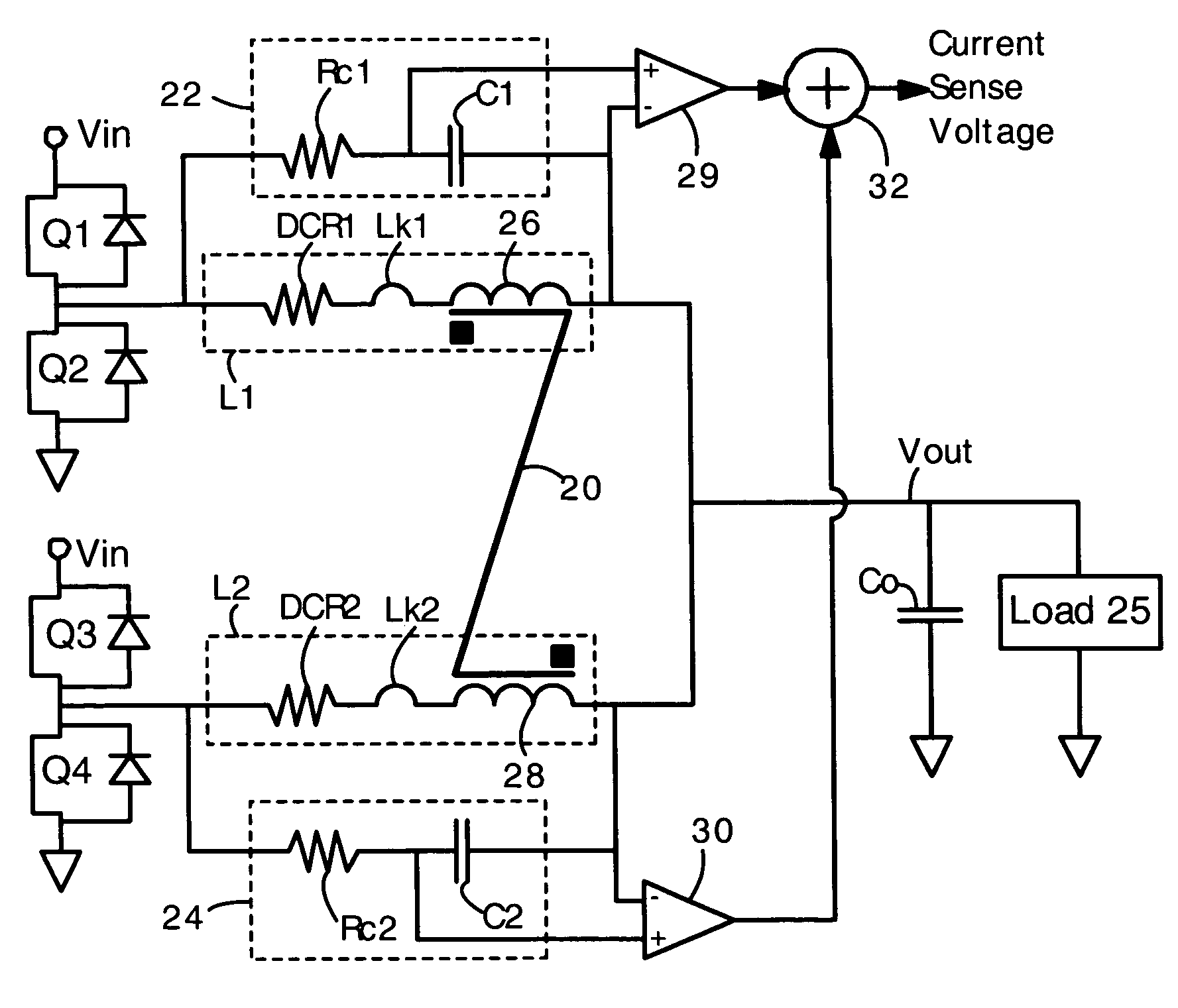
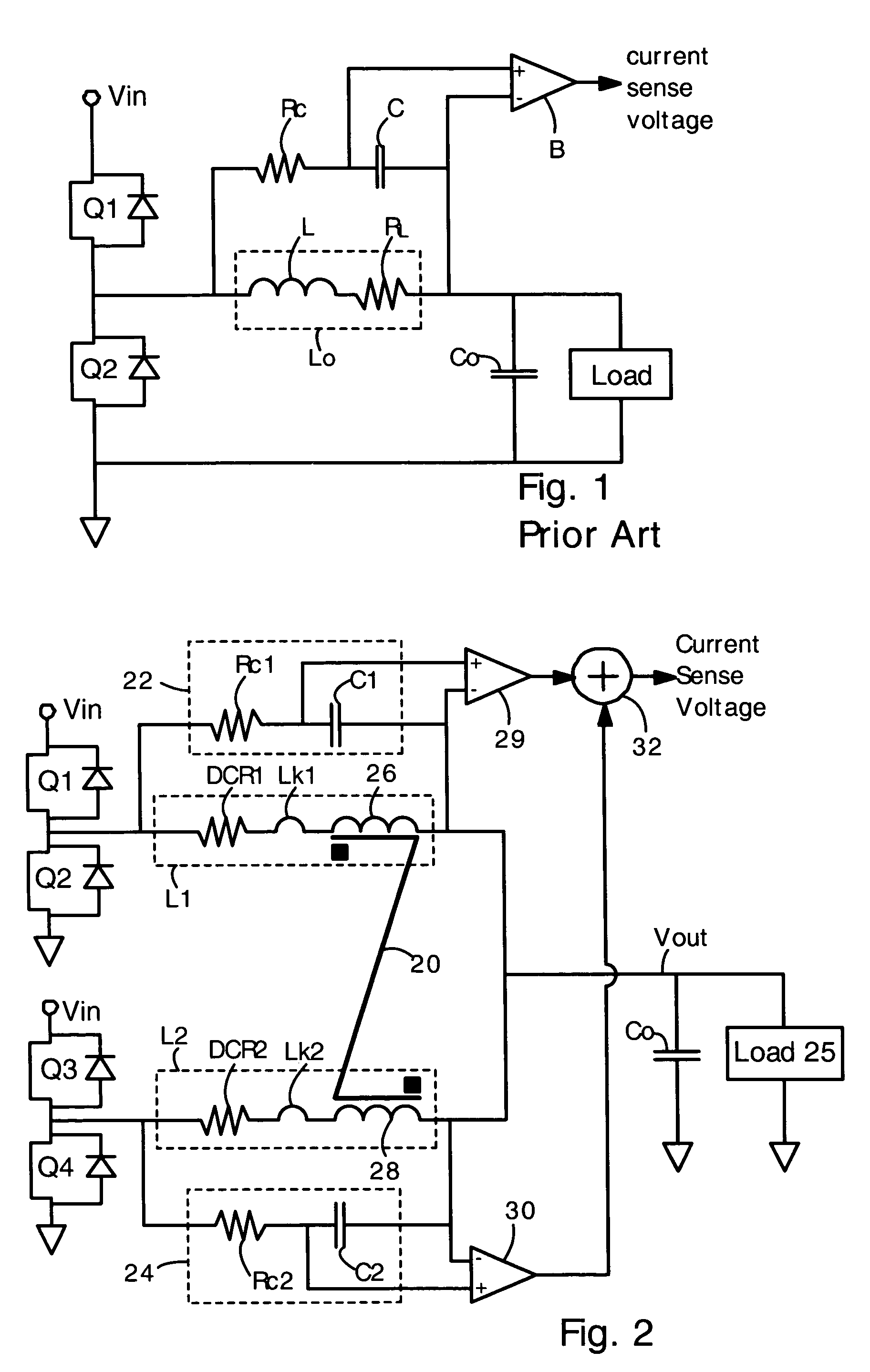
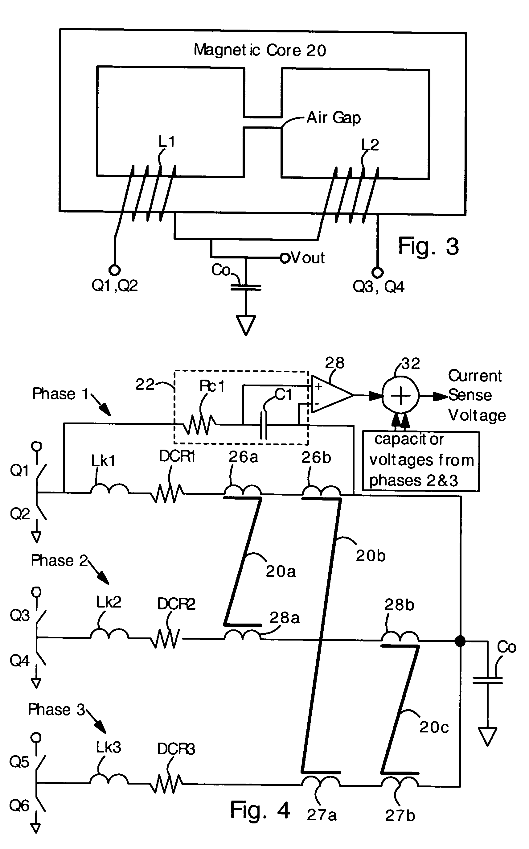
[0029]The present invention provides circuits for accurately sensing current flowing through coupled inductors. The present inventors have discovered that an RC circuit (comprising a resistor and capacitor connected in series) connected across each of two or more coupled inductors can be used to sense a sum of currents through the inductors if the RC time constant is matched to Lk / R, where Lk is the leakage inductance and R is the DC (ohmic) resistance of the inductor. In other words, the mutual inductance of a coupled inductor does not affect the time constant matching required between the inductor and the RC circuit. The present invention allows DCR current sensing techniques to be applied to coupled inductors and multi-phase voltage regulators. The present invention can be used for accurate current sensing in multiple phase voltage regulators, which commonly have coupled inductors.

[0030]In the present specification, “leakage inductance” is defined as the portion of an inductors i...


PUM


Abstract

Voltage regulators often have coupled output inductors because coupled output inductors provide improvements in cost and efficiency. Coupled inductors are often used in multi-phase voltage regulators. Feedback control of voltage regulators often requires accurate and responsive sensing of output current. Provided is a technique for accurately sensing the magnitude of output current in coupled inductors. An RC circuit (comprising a resistor and capacitor in series) is connected in parallel with the coupled inductor. The inductor has a leakage inductance Lk and a DC (ohmic) resistance of DCR. The resistor and capacitor are selected such that an RC time constant is equal to an L/R time constant of Lk/DCR. With the matching time constants, a sum of voltages on the capacitors is accurately proportional to a sum of currents flowing in the output inductors. Also provided is a technique for sensing current when an uncoupled center tap inductor is present.

Description

FIELD OF THE INVENTION[0001]The present invention relates generally to sensing electrical current flowing through coupled inductors. More specifically, it relates to a DC resistance (DCR) technique for sensing current flowing through coupled output inductors in a voltage regulator or DC to DC converter.BACKGROUND OF THE INVENTION[0002]Voltage regulators (VRs) and DC-to-DC converters are widely used for providing electrical power for computer processors and telecommunications electronics. Many voltage regulators include circuits for measuring output current and voltage so that feedback control of the voltage regulator is possible. One method for feedback control is adaptive voltage positioning (AVP), in which the output voltage is controlled in response to the output current. AVP is particularly well suited for use in microprocessor voltage regulators and voltage regulators for memory and graphics-processing circuits. AVP typically requires accurate and high speed sensing of output c...

Claims


Application Information

Patent Timeline
IPC IPC(8): G05F1/575G05F1/618
CPCH02M3/1584H02M1/0009
Inventor DONG, YANXU, MINGLEE, FRED C.
Owner VIRGINIA TECH INTPROP PROPERTIES
Why Eureka
Try Eureka