Engine fan control system and method

a technology of fan control system and engine, applied in the direction of efficient regulation technology, machines/engines, mechanical equipment, etc., can solve the problems of engine and/or machine components damage, engine and/or engine heat generation during operation, and reduce fuel efficiency

Active Publication Date: 2016-05-31
CATERPILLAR INC
View PDF15 Cites 2 Cited by
  • Summary
  • Abstract
  • Description
  • Claims
  • Application Information

AI Technical Summary

Problems solved by technology

Engines used to power mobile and stationary machines generate substantial amounts of heat during operation.
Heat, if not properly dealt with, can reduce fuel efficiency and / or cause damage to engine and / or machine components.
While it may be necessary and / or efficient to run the fan at a high speed under the former circumstance, it may be unnecessary and / or inefficient to run the fan at the same high speed under the later circumstance.
This time lag may result in certain engine components experiencing thermal fatigue, reduced fuel economy and increased emissions or emission shifting.
The time lag problem is also exacerbated in certain machine work cycles where the engine workload and other environmental conditions may change continuously.
However, it takes time for the coolant temperature to increase.
The required engine power decreases during these segments and therefore the cooling requirements decrease, but desired fan speed may remain unnecessarily at a maximum value due to the time lag.

Method used


Image

  • Engine fan control system and method
  • Engine fan control system and method
  • Engine fan control system and method

Examples


Embodiment Construction

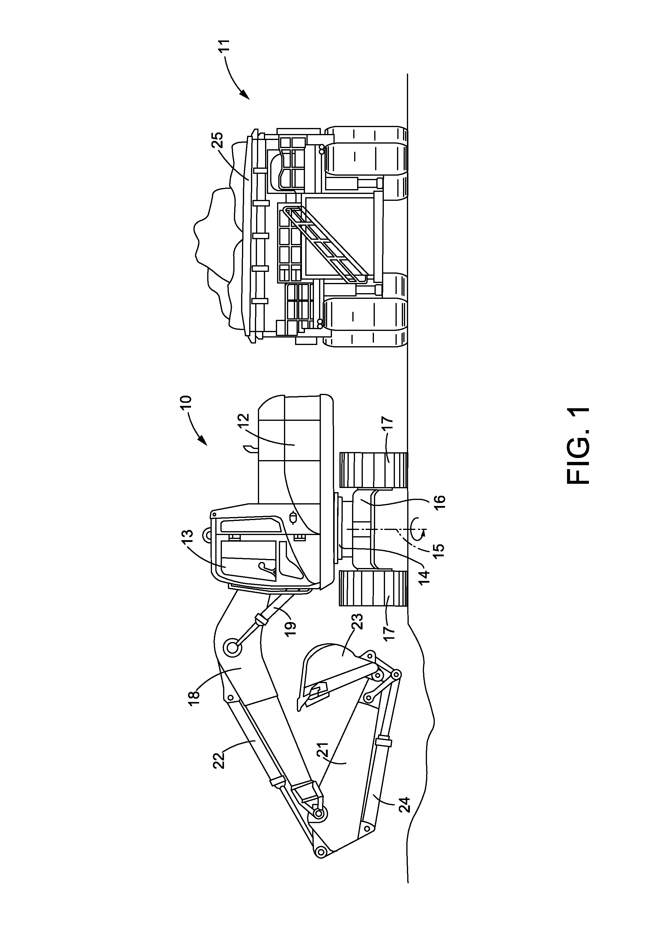
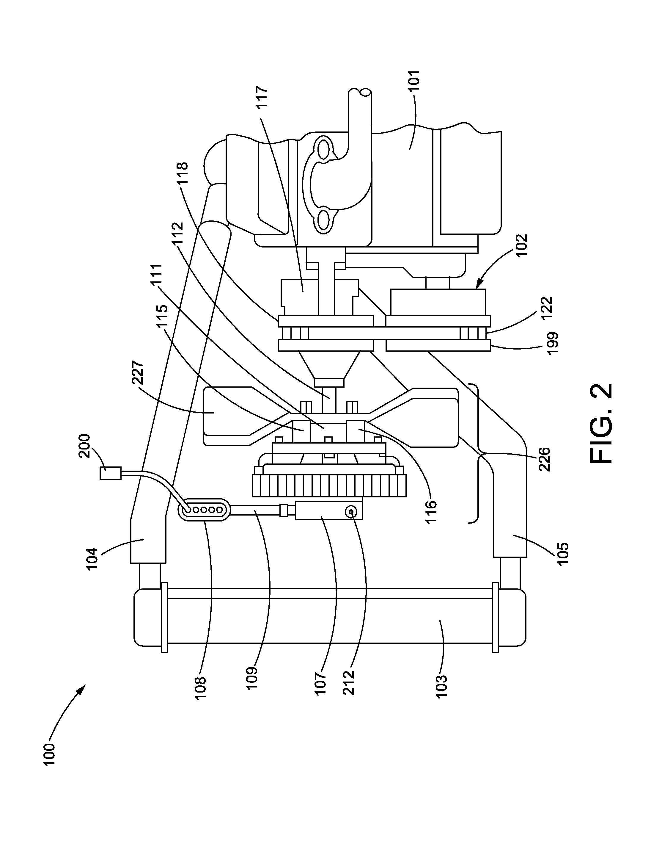
[0021]FIG. 1 illustrates an excavator 10 and a truck 11, both of which may include engines (not shown) with certain cooling requirements that may be satisfied at least in part by a fan cooling system 100 (also not shown in FIG. 1; see FIG. 2). The excavator 10 may include a chassis 12 and a cab 13, which may be supported by a turret 14. The turret 14 may be rotatable about a vertical axis 15. The turret 14 may be supported by an undercarriage 16, which may include or be coupled to numerous components for driving the ground engaging elements, which may be a pair of tracks 17. The chassis 12 may be coupled to a boom 18 and a boom cylinder 19. The boom 18 may be coupled to a stick 21 and a stick cylinder 22. The stick 21 may be coupled to a bucket 23 and a bucket cylinder 24.

[0022]In a typical cyclic or repetitive work cycle, the excavator 10 may carry out a dig operation or a dig segment in the position shown in FIG. 1 where the bucket 23 is at least partially filled with material. Af...


PUM


Abstract

This document discloses an adaptive fan control system for controlling a fan that cools an engine of a machine. Many machines carry out repetitive tasks or work cycles. The cooling requirements of the engine vary for each portion or segment of a work cycle. The disclosed system includes a controller with a memory having a plurality of stored work cycle patterns. Using a variety of sensors, the system and controller identifies the work cycle that the machine is carrying out and, using one of the stored work cycle patterns, the system anticipates the cooling requirements of the machine as the machine progresses through the work cycle and the system proactively changes the fan speed for upcoming segments of the work cycle.

Description

TECHNICAL FIELD[0001]This document discloses fan control systems and methods of controlling the speed of a fan used to cool an engine used to power a stationary or mobile machine.BACKGROUND[0002]Engines used to power mobile and stationary machines generate substantial amounts of heat during operation. Heat, if not properly dealt with, can reduce fuel efficiency and / or cause damage to engine and / or machine components. Such engines typically include cooling systems to remove heat from the engine during operation. The cooling systems may include, among other things, a fan configured to draw heat away from, and / or push cooling airflow toward the engine.[0003]In a typical cooling circuit for an internal combustion engine, coolant passes through a jacket surrounding the engine as the coolant temperature rises. The coolant then passes through the radiator, entering the radiator through a manifold and then passing through cooling tubes where air flows over the tubes to remove heat from and ...

Claims


Application Information

Patent Timeline
Patent Type & Authority Patents(United States)
IPC IPC(8): F01P7/04F04D19/00
CPCF01P7/04F04D19/002F05D2270/44F04D27/004Y02B30/70
Inventor GE, XINYUZHANG, KAI
Owner CATERPILLAR INC
Why Eureka
Try Eureka