DIN rail mounted enclosure assembly and method of use

a technology of enclosure and rail, applied in the field of electronic devices, can solve the problems of inconvenient use, time-consuming, and difficult removal of these larger devices, and achieve the effects of reducing the cost of installation and removal, and reducing the cost of us

Active Publication Date: 2016-06-21
SCHNEIDER ELECTRIC BUILDINGS AMERICAS INC
View PDF50 Cites 11 Cited by
  • Summary
  • Abstract
  • Description
  • Claims
  • Application Information

AI Technical Summary

Problems solved by technology

Installing or removing these larger devices can be very difficult, particularly for devices that are of a size that requires two or more DIN clips.
Such removal can prove to be very difficult, time consuming, and counter-intuitive for users. FIG. 1 shows an example of a prior art mounting assembly generally indicated at 5 having two conventional DIN clips, each indicated at 8, as described above.

Method used


Image

  • DIN rail mounted enclosure assembly and method of use
  • DIN rail mounted enclosure assembly and method of use
  • DIN rail mounted enclosure assembly and method of use

Examples


Embodiment Construction

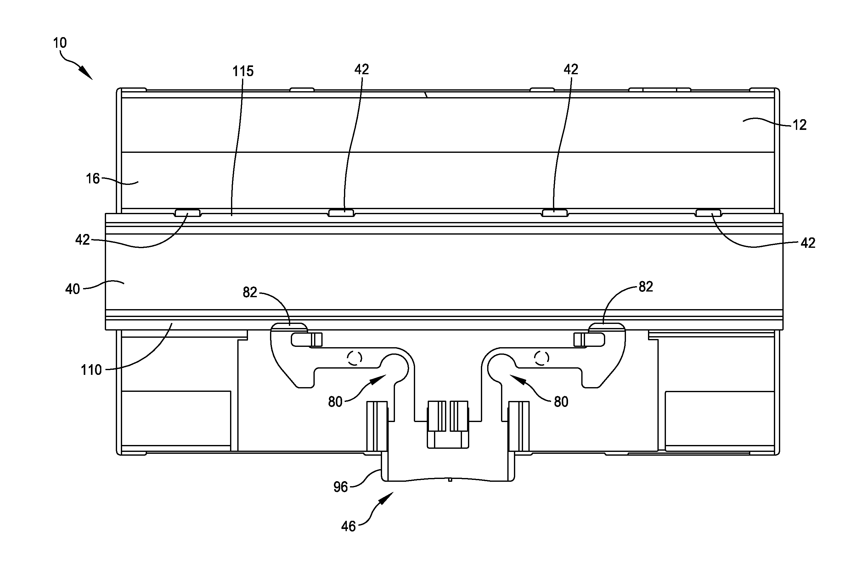
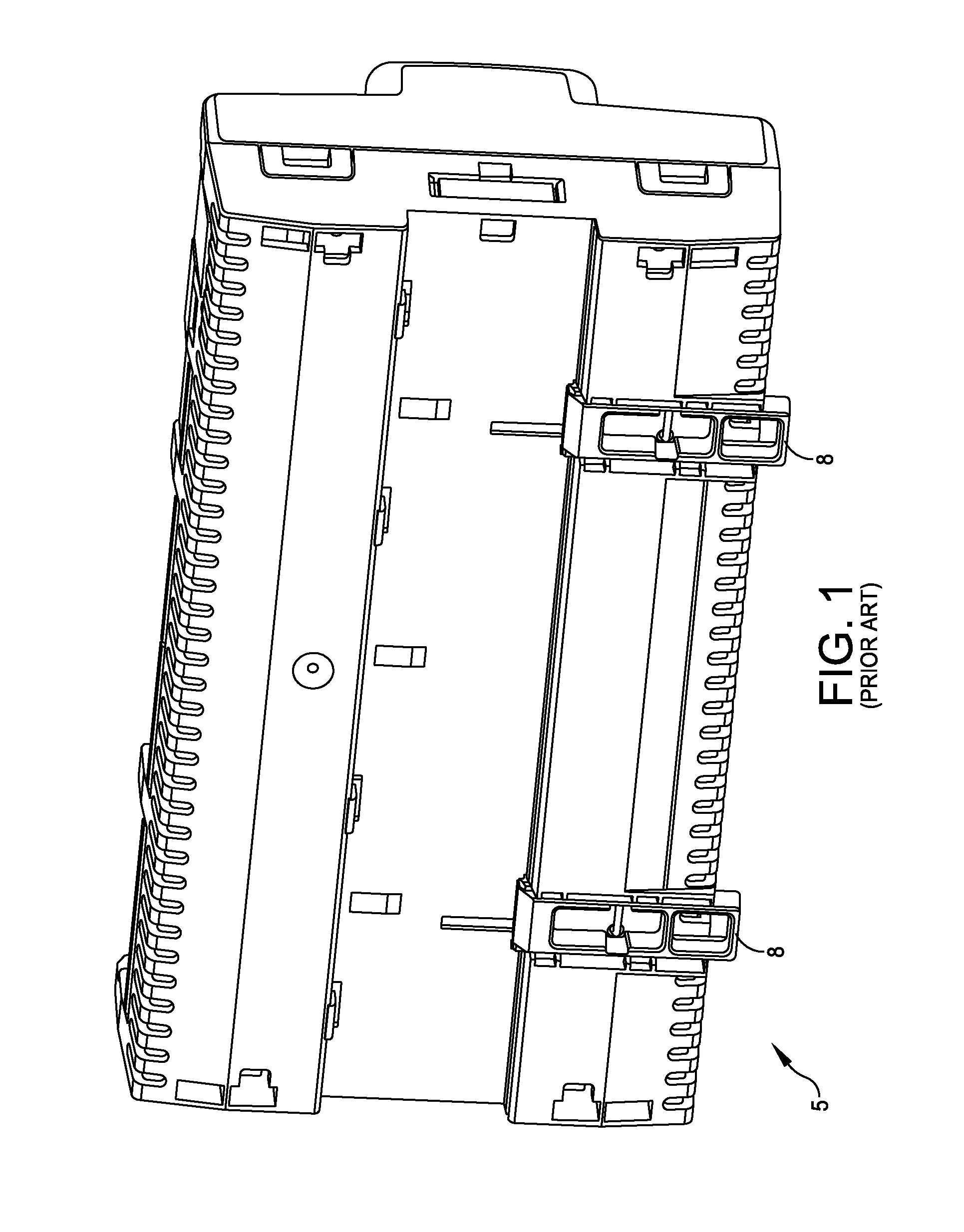
[0026]As discussed above, traditional DIN clips suffer from disadvantages related to the effort required to disengage or otherwise release a mounting enclosure assembly from a DIN rail. Accordingly, there is a need for a more efficient DIN clip, also referred to as a locking mechanism.

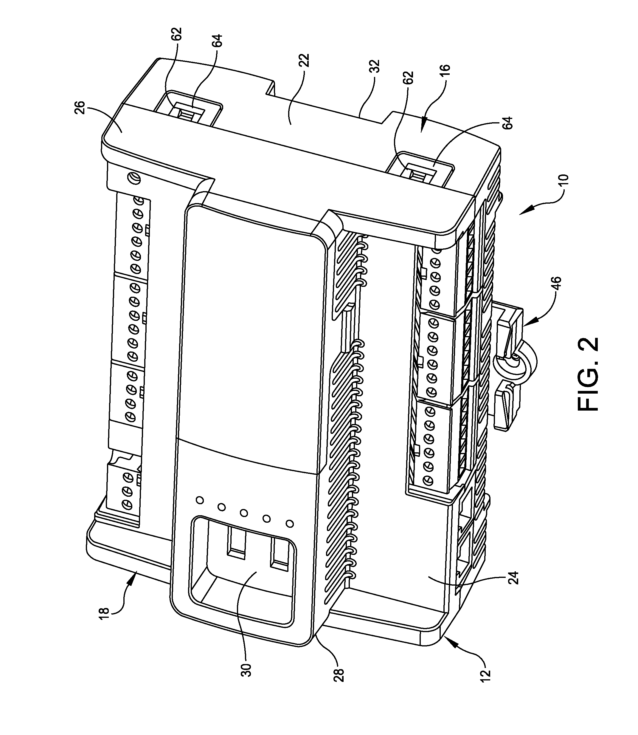
[0027]The systems and methods disclosed herein provide a push-button locking mechanism that achieves the same holding strength as two common DIN clips. The locking mechanism is conducive to one-handed operation and requires no tools. The locking mechanism may be molded from a PC / ABS plastic resin and may be assembled into a plastic base housing during manufacturing.

[0028]Basic operation consists of pushing a release button with, for example, a person's thumb, to engage and disengage the assembly from the DIN Rail. When the release button is pushed, a DIN clip protrusion moves away from the DIN rail, thereby disengaging the assembly from the DIN rail and allowing the assembly to be lifted off or on when...


PUM


Abstract

A mounting enclosure assembly configured to mount an electronic component onto a DIN rail. The mounting enclosure assembly includes a mounting bracket having a slot configured to receive the DIN rail therein. The mounting enclosure assembly further includes a locking mechanism configured to selectively engage the DIN rail. The locking mechanism includes a release button and a protrusion positioned proximate the slot and configured to releasably engage a first flange of the DIN rail. The locking mechanism further includes a first hinged armature connected to the release button and the first protrusion, wherein the first protrusion is configured to disengage the first flange of the DIN rail when the release button is depressed. Other embodiments of the mounting enclosure assembly, as well as methods directed to the mounting enclosure assembly, are further disclosed.

Description

BACKGROUND[0001]1. Field of Disclosure[0002]The present disclosure relates generally to the field of electronics and, more particularly, to assemblies and methods for securing and removing electronic components to and from a rail system, such as a DIN rail system.[0003]2. Discussion of Related Art[0004]Current DIN-mounted devices are designed with a single DIN clip or multiple DIN clips that require a tool and two hands when installing or removing the device from a standard 35 mm DIN rail. Installing or removing these larger devices can be very difficult, particularly for devices that are of a size that requires two or more DIN clips. For example, when trying to remove a larger device one typically needs to push one DIN clip in a downward direction with a tool to disengage the device from the DIN rail. While holding up that portion of the device with one hand to prevent reattachment, one must use their other hand to release the other DIN clip with the tool. Such removal can prove to...

Claims


Application Information

Patent Timeline
Patent Type & Authority Patents(United States)
IPC IPC(8): A47B96/00H05K7/18H05K7/14
CPCH05K7/1401H05K7/183H05K7/1474
Inventor BORETTI, DAVID
Owner SCHNEIDER ELECTRIC BUILDINGS AMERICAS INC
Why Eureka
Try Eureka