Screwless sash lock for metal and plastic window sashes and the like

a sash lock and metal and plastic technology, applied in the direction of wing knobs, manufacturing tools, mechanical equipment, etc., can solve the problem of downward deformation of the foot, and achieve the effect of reducing or eliminating the deformation

Inactive Publication Date: 2016-06-28
VISION INDS GROUP
View PDF9 Cites 11 Cited by
  • Summary
  • Abstract
  • Description
  • Claims
  • Application Information

AI Technical Summary

Benefits of technology

[0005]It is an object of the invention to provide a sash lock that may be easily and quickly secured to, and / or removed from, a sash window or a sash door.
[0007]It is a further object of the invention to provide a sash lock housing that may be removed from a sash window / door without requiring the removal of mechanical fasteners.
[0012]Installation of the screwless sash lock onto the meeting rail of the sash window / door may occur by first inserting the foot of the first leg of the lock housing, at an angle, so as to enter through the first elongated opening in the meeting rail. Next, rotation of the screwless sash lock permits the foot of the second leg to become proximate to the second elongated opening in the meeting rail, with a top surface of the foot of the first leg contacting the underside of the rail-stile wall, and with the locking protrusion contacting the rail-stile wall outside of the cavity. Pressure may then be applied to the second end of the housing to cause deformation of the housing and / or rail, to thereby force the foot of the second leg to enter through the second elongated opening to be disposed within the hollow rail / stile. Transitioning to application of a sliding force upon the screwless sash lock housing, in the same direction as the foot of the first and second legs, results in the angled top surface of the foot of the second leg causing downward deformation of the foot relative to the housing bottom surface, until the apex contacts the underside of the rail / stile wall, which results in a friction fit between the rail / stile wall, and the housing foot apex and housing bottom surface. Continued sliding of the screwless sash lock until the locking tab is received in the third opening in the rail will reduce or eliminate the deformation, with the bottom surface of the housing becoming flush with a top surface of the rail / stile wall, and with a side surface of the first and second legs contacting the first and second elongated openings to have the housing cover the first, second and third rail openings.

Problems solved by technology

Transitioning to application of a sliding force upon the screwless sash lock housing, in the same direction as the foot of the first and second legs, results in the angled top surface of the foot of the second leg causing downward deformation of the foot relative to the housing bottom surface, until the apex contacts the underside of the rail / stile wall, which results in a friction fit between the rail / stile wall, and the housing foot apex and housing bottom surface.

Method used


Image

  • Screwless sash lock for metal and plastic window sashes and the like
  • Screwless sash lock for metal and plastic window sashes and the like
  • Screwless sash lock for metal and plastic window sashes and the like

Examples


Embodiment Construction

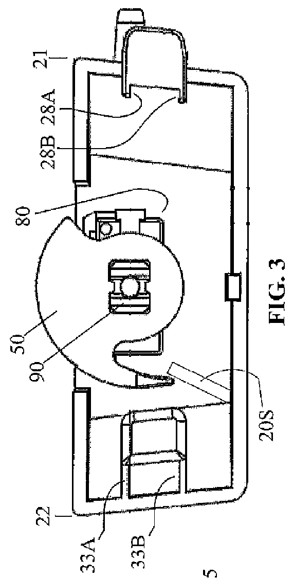
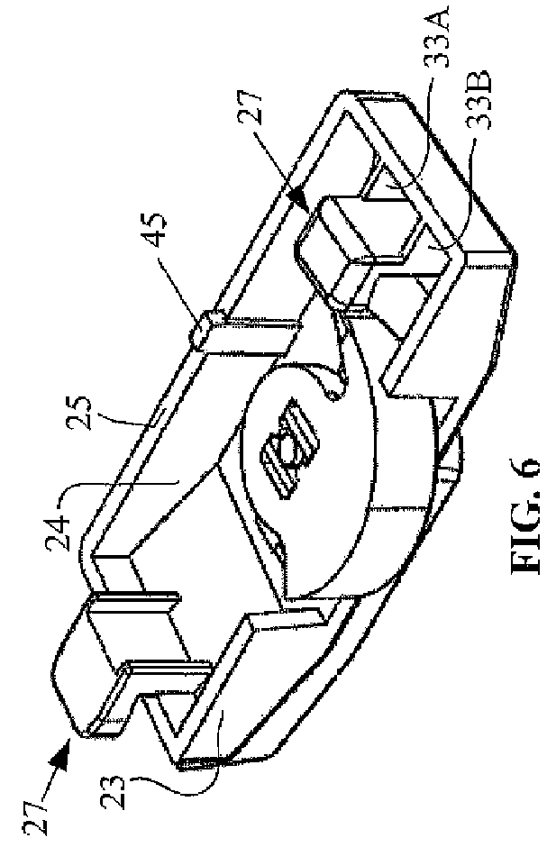
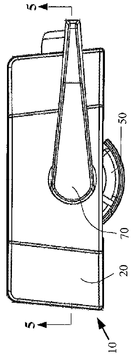
[0083]A first embodiment of the screwless sash lock 10 according to the current invention is shown in FIGS. 1-6. The screwless sash lock 10 may be installed onto a sash window or door that has already been installed into a building, or the sash lock 10 may be installed during the assembly of the window and prior to its installation. As seen in the exploded view of FIG. 7, parts comprising the screwless sash lock 10 may include a housing 20, a cam 50, a shaft 70, a spring 80, and a wedge 90.

[0084]The housing 10, as well as the other component parts of the lock, may be a metallic material and be formed through a machining, forging or casting process, or may be made of a plastic material and be formed through an injection molding process, or it may be a composite part. The housing 20 may be dome-shaped, or rectangular, or elongated, or any other suitable shape. The housing 20 may have a first end 21, a second end 22, and may comprise only a single, integrally formed housing wall with a...


PUM

PropertyMeasurementUnit
rotationaaaaaaaaaa
torqueaaaaaaaaaa
angleaaaaaaaaaa

Abstract

A lock adapted for attachment to a sash window / door without screws comprises: a shaft with a cam secured thereon is rotatably secured to a housing, with the cam disposed within a housing cavity and rotatable therefrom out of an opening, into an extended position. The housing may be a single integrally formed wall that preferably has a flat bottom surface. A first attachment leg protrudes out from the housing cavity to extend beyond the bottom surface, with a foot thereon extending beyond a first end of the housing. A second attachment leg protrudes out the housing cavity second end, with a foot thereon oriented toward the housing first end, and a locking tab extends from the housing bottom surface. Installation of the screwless sash lock is by receiving the first foot, second foot, and locking tab within correspondingly positioned openings in the window / door rail, through sequenced rotational and sliding motion.

Description

CROSS REFERENCES TO RELATED APPLICATIONS[0001]This application claims priority on U.S. Provisional Application Ser. No. 61 / 518,798 having the title, “Sash Lock for Metal and Plastic Window Sashes and the Like,” filed on May 11, 2011, the disclosures of which are incorporated herein by reference.FIELD OF THE INVENTION[0002]The present invention is directed to improvements in sash locks and handles, and more particularly to a screwless means for securing sash locks to window sashes that are hollow in at least the region where the sash lock is secured to the window sash.BACKGROUND OF THE INVENTION[0003]There are scores of issued sash lock utility patents, which invariably utilize screws for mounting of the lock to a window. See, for example, U.S. Pat. No. 7,731,251 to Ye for “Compact Sliding Sash Lock”; U.S. Pat. No. 7,017,957 to Murphy for “Sash Lock for Sash Window”; and U.S. Pat. No. 6,142,541 to Rotondi for “Pick Resistant Sash Lock.” The use of separate mechanical fasteners for mo...

Claims


Application Information

Patent Timeline
Patent Type & Authority Patents(United States)
IPC IPC(8): E05B1/00E05B9/08E05C3/04E05C7/00
CPCE05B9/08E05C3/046E05B1/0015E05C2007/007Y10T29/49876Y10T292/1056Y10T292/1077
Inventor LIANG, LUKELIANG, TONGCHEN, DAVID
Owner VISION INDS GROUP
Why Eureka
Try Eureka