
Removable closure assembly for a water treatment system

a technology of fluid treatment chamber and closure, which is applied in the direction of containers preventing decay, rigid containers, packaging, etc., can solve the problems of o-rings being compressed between the fluid treatment chamber and the closure for long periods of time, and the closures are difficult to remove or install, so as to achieve convenient and quick removal and secure the

Inactive Publication Date: 2006-01-10
ACCESS BUSINESS GRP INT LLC
View PDF24 Cites 11 Cited by
  • Summary
  • Abstract
  • Description
  • Claims
  • Application Information

AI Technical Summary

Benefits of technology

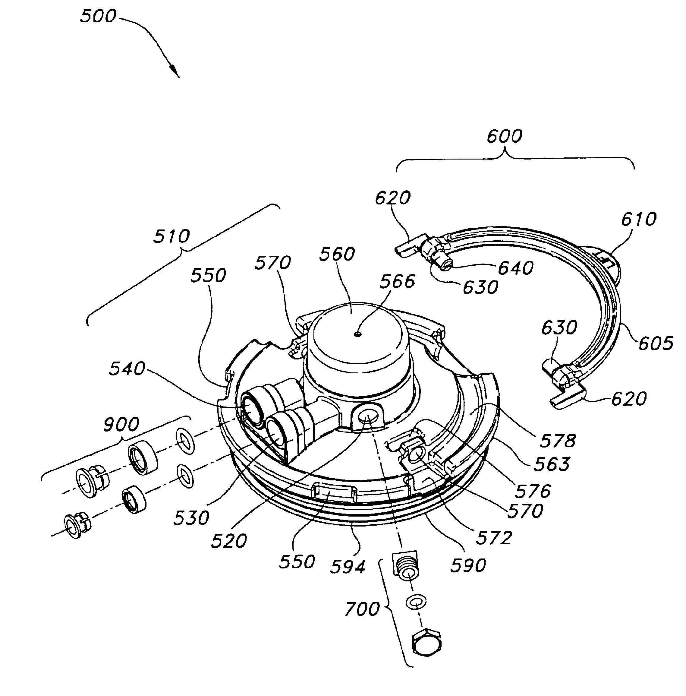
The present invention is a unique closure assembly for a water treatment system (WTS) that is easy to install and remove. The closure assembly has a bail handle that uses a mechanical advantage to break the seal between the closure and the WTS fluid treatment chamber, lifting the closure away from the chamber. The closure is designed to be easily installed and removed even after extended periods of use. The closure also has an ergonomic lifting mechanism that allows for easy removal from the WTS fluid treatment chamber. Overall, the closure assembly provides a convenient and efficient solution for accessing and closing the WTS.

Problems solved by technology

A first problem many WTS units encounter is that fluid treatment chamber closures can be difficult to remove or install.
The large diameter results in a relatively large contact surface between the chamber and the chamber closure, requiring a relatively large force to remove the closure from the fluid treatment chamber.
Some filters only require annual replacement, causing the o-ring to be compressed between the fluid treatment chamber and closure for long periods of time.
Consequently, high break-out force is required to overcome this set when removing the closure.
After water has not been run through a WTS unit for a significant period of time, such as overnight, heat from the UV bulb and other electrical circuitry can cause heat to build up inside and elevate the temperature of water stored within the fluid treatment chamber.
The resulting increased temperature contributes to plastic creep and the “welding” together of the threaded connection between the closure and treatment chamber, or to the set between the o-ring and adjacent sealing surfaces.
A problem with this type of mount is that a closure must be accurately aligned with the WTS fluid treatment compartment to effect mounting of the closure to the fluid treatment chamber.
Also, even with a bayonet mount, there is still significant joint contact area between the closure, o-ring seals, and the fluid treatment housing.
Again, significant force may be required to break the closure free from the fluid treatment chamber after a long period of attachment.
This type of closure assembly requires relatively complex linkage and fluid treatment chamber design to effectuate a seal between the closure and the fluid treatment chamber.

Method used


Image

  • Removable closure assembly for a water treatment system
  • Removable closure assembly for a water treatment system
  • Removable closure assembly for a water treatment system

Examples


Embodiment Construction

[0034]The present invention is not limited in its application to the details of construction and arrangement of parts as illustrated in the accompanying drawings and specifications. For purposes of disclosure, embodiments of the closure assembly of the present invention will be described in connection with a water treatment system (WTS), and more specifically in connection with a WTS that relies on a carbon-based filter to filter particulates and remove certain contaminants, and an ultraviolet (UV) lamp to destroy microorganisms in water. Although described in connection with this particular application, one skilled in the arts would recognize that the present invention is capable of being practiced in various ways within the scope of the claims.

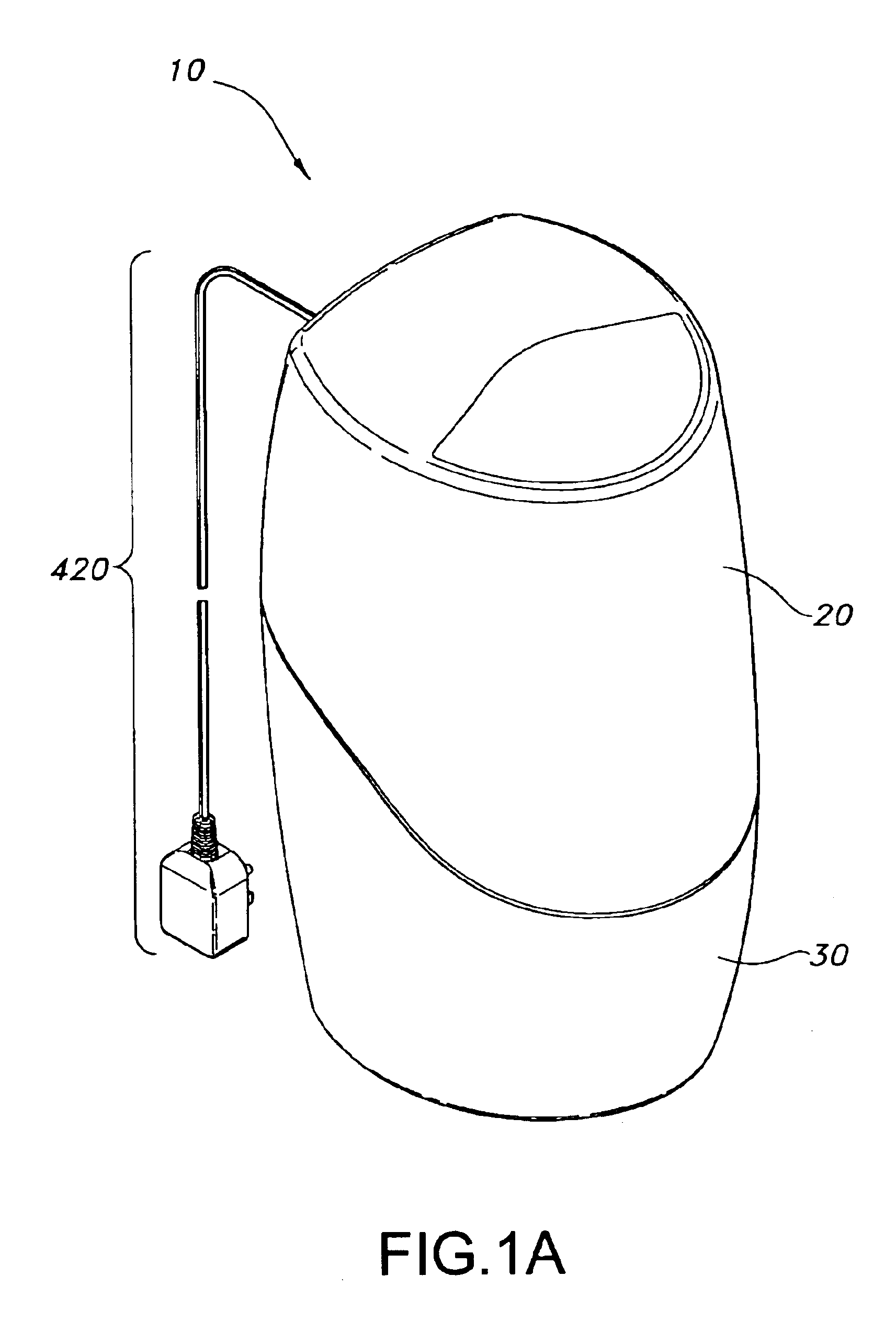
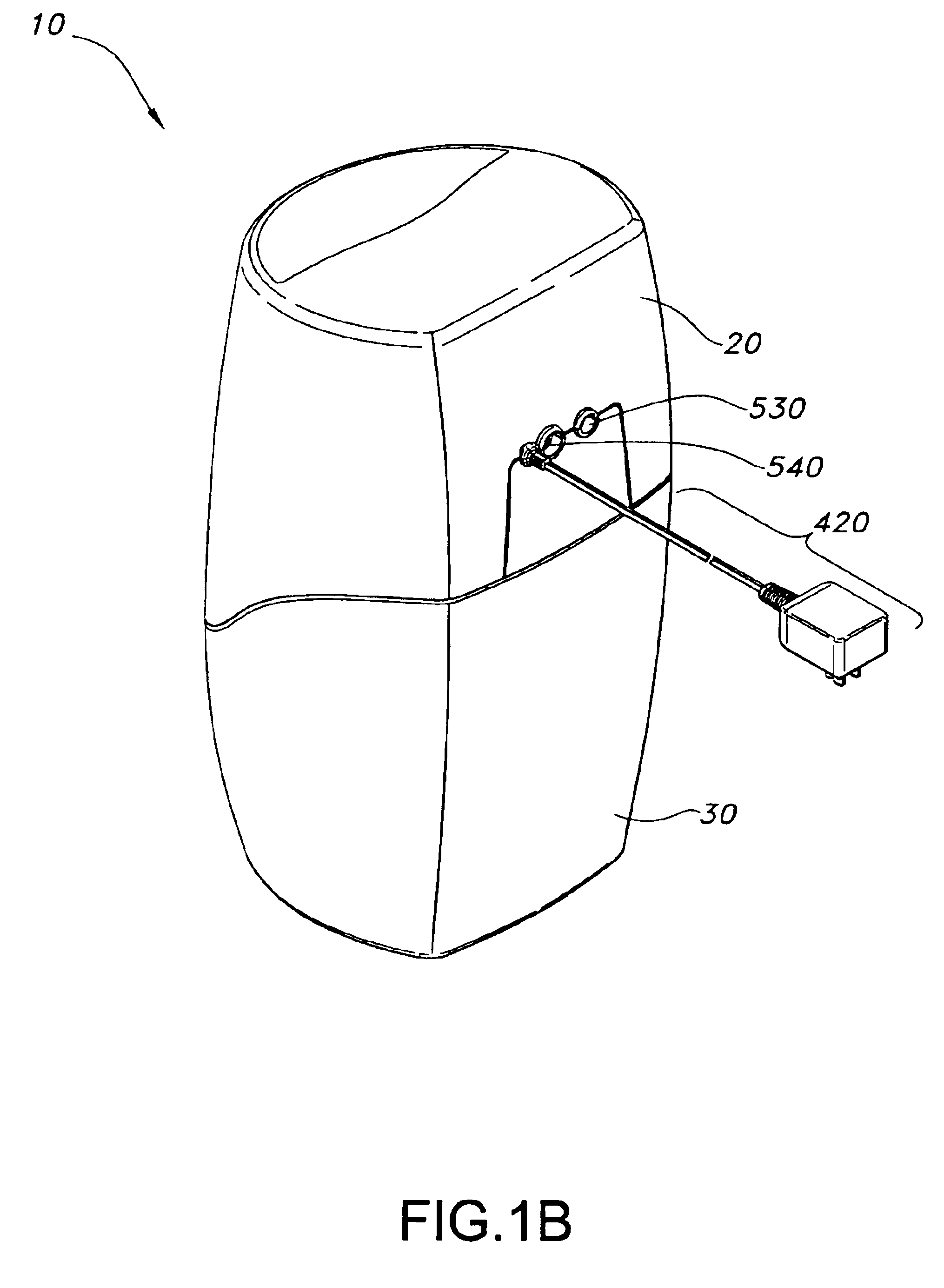
[0035]FIGS. 1A and 1B provide two perspective views of a typical water treatment system (WTS) 10 that incorporates the closure assembly of the present invention. WTS 10 includes top shroud 20, base housing 30, power supply cord 420, treated ...


PUM

PropertyMeasurementUnit
diametersaaaaaaaaaa
diameteraaaaaaaaaa
timeaaaaaaaaaa

Abstract

The present invention provides a WTS closure assembly that is easily and quickly secured to and removed from the filter chamber of a WTS. The closure assembly of the present invention provides a bail handle attached to the closure and which utilizes a mechanical advantage, preferably in the form of a pivoting handle which presses a plurality of cams onto the WTS housing, thereby breaking a seal between the closure assembly and the WTS filter chamber, and lifting the closure away from the filter chamber.

Description

INCORPORATION BY REFERENCE[0001]The present invention claims benefit under 35 USC §119(e) of U.S. provisional patent application Ser. No. 60 / 357,908, entitled “Point Of Use Water Treatment System” filed on Feb. 19, 2002.[0002]This application hereby incorporates in their entirety by reference issued U.S. Pat. No. 6,436,299 entitled “Water Treatment System with an Inductively Coupled Ballast”, issued U.S. Pat. No. 6,245,229 entitled “Point Of Use Water Treatment System”, and issued U.S. Pat. No. 5,344,558 entitled “Water Filter Cartridge”.TECHNICAL FIELD[0003]The present invention relates to a removable closure assembly for use with a water treatment system used in homes and offices to filter and treat contaminants in water and equipped with one or more filter compartments.BACKGROUND OF THE INVENTION[0004]The present invention minimizes or overcomes several problems associated with previous point-of-use home or office water treatment system (WTS) units. These WTS units often include ...

Claims


Application Information

Patent Timeline
Patent Type & Authority Patents(United States)
IPC IPC(8): B01D35/30C02F1/32C02F9/12B01D35/04C02F1/28C02F9/00H01J5/52H01J61/56H05B37/02H05B41/04H05B41/10H05B41/18H05B41/24H05B41/295H05B41/36
CPCB01D35/30H05B41/36H01J5/52H01J61/56H05B41/10H05B41/295C02F9/005B01D2201/301B01D2201/34C02F1/283C02F1/32C02F2201/006C02F9/20B65D45/00
Inventor BARTKUS, ERIC K.CONRAD, KENNETH E.DEKKER, DAVID J.
Owner ACCESS BUSINESS GRP INT LLC
Learn More