Methods of controlling an outdoor lighting system

a technology of outdoor lighting and control methods, applied in the direction of electric variable regulation, process and machine control, instruments, etc., can solve the problems that the activity information provided by the detection system is not immediately suitable and the information of the detection system is not yet used for controlling the outdoor lighting system

Active Publication Date: 2016-07-05
SIGNIFY HLDG BV
View PDF19 Cites 2 Cited by
  • Summary
  • Abstract
  • Description
  • Claims
  • Application Information

AI Technical Summary

Benefits of technology

[0005]It is an object of the invention to provide a solution enabling controlling the light intensity of street lighting in a more economical manner.

Problems solved by technology

However, the information of the detection systems is not yet used for controlling the outdoor lighting systems.
However, the sub-areas of the detection system are different from the spatial segments of the outdoor lighting system and the activity information that is provided by the detection system is not immediately suitable for controlling an outdoor lighting system.

Method used


Image

  • Methods of controlling an outdoor lighting system
  • Methods of controlling an outdoor lighting system
  • Methods of controlling an outdoor lighting system

Examples


Embodiment Construction

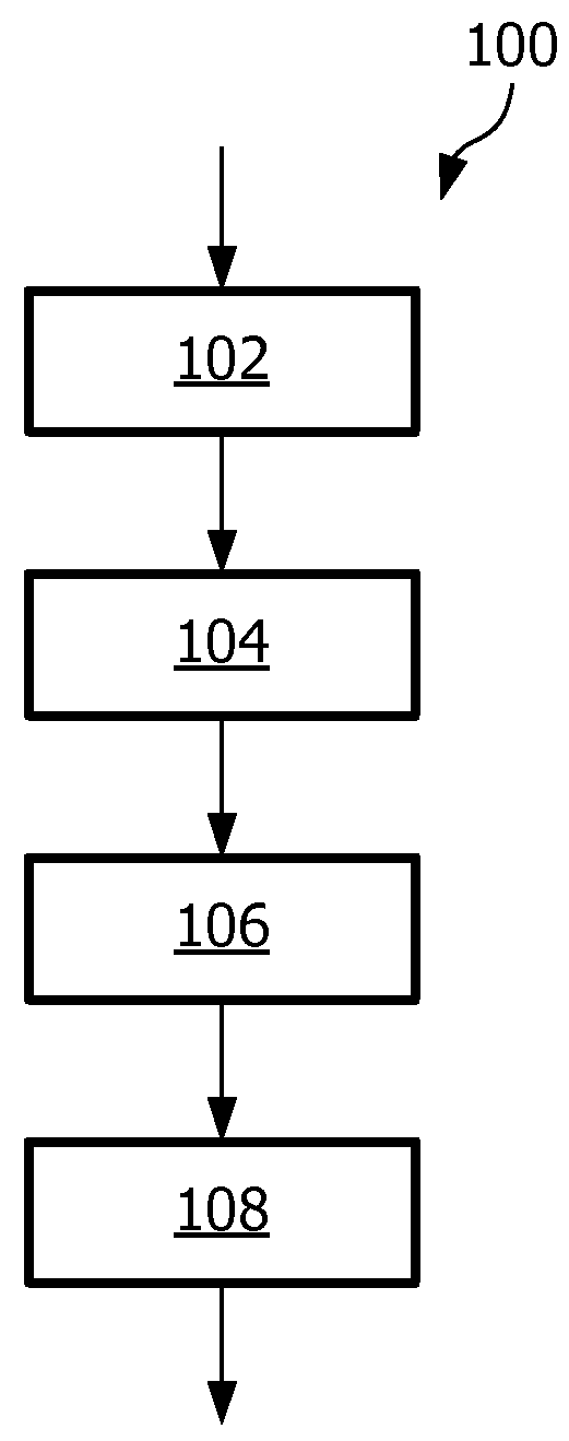
[0059]In FIG. 1 an embodiment of a method 100 according to the first aspect of the invention is shown. The method is suitable for controlling an outdoor lighting system. The outdoor lighting system comprises outdoor lamps which are distributed over spatial segments of an outdoor space. The outdoor lamps of a specific spatial segment illuminate the spatial segment with a controllable light intensity. In step 102 of the method an indication of a sub-area and an activity property for the sub-area are received from a detection system. The detection system detects activity in sub-areas of the outdoor space. At least one sub-area is different from all the spatial segments of the outdoor lighting system. In step 104 the indication of the sub-area is transformed to one or more indications of one or more spatial segments. In step 106 the light intensity level for each one of the one or more spatial segments is determined in dependence on the activity property. In step 108 the one or more ind...


PUM


Abstract

A method (100) of controlling an outdoor lighting system, a computer program product, a controlling device for controlling an outdoor lighting system and an outdoor lighting system are provided. The outdoor lighting system comprises outdoor lamps which are distributed over spatial segments of an outdoor space. The emitted light intensity of the outdoor lamps is controllable per spatial segment, and references are used to refer to specific spatial segments. The method (100) comprises the steps of (i) receiving (102) from a detection system an indication of a sub-area of the outdoor space and receiving at least one activity property or the sub-area, the detection system being arranged for detecting activity in the sub-area, the sub-area being different from all the spatial segments, and the indication being used to refer to the sub-area, and the at least one activity property being related to a traffic density in the sub-area (ii) mapping (104) the at least one indication to at least one reference of a respective spatial segment, (iii) determining (106) a light intensity level for the respective at least one spatial segment in dependence on the received at least one activity property, (iv) providing (108) the at least one reference together with the respective determined light intensity to the outdoor lighting system.

Description

FIELD OF THE INVENTION[0001]The invention relates to methods and systems for controlling an outdoor lighting system.BACKGROUND OF THE INVENTION[0002]Many state of the art street lighting systems have the capability of dimming the light of the street lamps such that energy may be saved. The street lamps are, for example, dimmed to a lower light intensity between 11:00 pm and 5:00 am. The reduction of the emitted light intensity during these hours is possible because of the relatively low average traffic intensity during these hours. Street lighting systems are often subdivided into segments of streets lamps with a fixed length of, for example, 2 km. At intersections the segments have often different lengths. The desired light intensity emitted by the street lamps of each one of the segments may be controlled from a central location.[0003]Published UK patent application G2444734A discloses an energy-efficient road lighting employing presence detection. The road lighting system has a d...

Claims


Application Information

Patent Timeline
Patent Type & Authority Patents(United States)
IPC IPC(8): H05B37/02
CPCH05B37/0227H05B37/0272Y02B20/72H05B47/19H05B47/125Y02B20/40H05B47/115H05B47/13
Inventor KNIBBE, ENGEL JOHANNESBONNE, NOEL FRANCOIS LEOPOLD
Owner SIGNIFY HLDG BV
Why Eureka
Try Eureka