
Apparatus and method for a natural draft air cooled condenser cooling tower

a cooling tower and air cooled technology, applied in the direction of indirect heat exchangers, machines/engines, lighting and heating apparatus, etc., can solve the problems of expansion and contraction of ducts and cooling surfaces, wet or dry cooling towers, and difficult to efficiently and effectively direct steam to all the inner surface areas of the condenser

Active Publication Date: 2014-04-29
SPG DRY COOLING USA LLC
View PDF10 Cites 3 Cited by
  • Summary
  • Abstract
  • Description
  • Claims
  • Application Information

AI Technical Summary

Benefits of technology

This configuration ensures even steam distribution, reduces maintenance costs by eliminating the need for expensive expansion joints, and provides adjustable airflow control to optimize cooling capacity and prevent overheating or freezing, enhancing the overall efficiency and reliability of the cooling tower.

Problems solved by technology

Cooling towers may be wet or dry.
To accomplish the cooling required the condenser requires a large surface area to dissipate the thermal energy in the gas or steam and presents several problems to the design engineer.
It is difficult to efficiently and effectively direct the steam to all the inner surface areas of the condenser because of nonuniformity in the delivery of the steam due to system ducting pressure losses and velocity distribution.
Another problem with the current air cooled condensers is the expansion and contraction of the ducts and cooling surfaces caused by the temperature differentials.
These expansion accommodating devices are expensive.
These devices usually do not incorporate a natural draft shell because the fans replace the chimney effect of the natural draft cooling towers.
However, forced draft fans may be incorporated in a natural draft design to supplement airflow where the density difference described above is not sufficient to produce the desired airflow.
However, even in the wide open position a pressure loss through the damper occurs.
This pressure loss reduces the total airflow and thus the cooling capacity of the tower.
Additionally, due to temperature and humidity extremes, a natural draft cooling tower may extract too much heat energy out of the heated liquid or have the liquid to be cooled freeze up.
For example, a dry cooling tower may extract too much thermal energy away from the heated liquid condensate, which would require extra heating energy from a boiler or heat source to reheat the liquid back to its optimal temperature, thus lowering the system's efficiency.
A wet tower on the other hand is susceptible to ice formation in cold weather.
In particular ice may form and build up in the fill and cause structural damage to the fill and / or the supporting structure.

Method used


Image

  • Apparatus and method for a natural draft air cooled condenser cooling tower
  • Apparatus and method for a natural draft air cooled condenser cooling tower
  • Apparatus and method for a natural draft air cooled condenser cooling tower

Examples


Embodiment Construction

[0039]In the following detailed description, reference is made to the accompanying drawings, which form a part hereof and show by way of illustration specific embodiments in which the invention may be practiced. These embodiments are described in sufficient detail to enable those skilled in the art to practice them, and it is to be understood that other embodiments may be utilized, and that structural, logical, processing, and electrical changes may be made. It should be appreciated that any list of materials or arrangements of elements is for example purposes only and is by no means intended to be exhaustive. The progression of processing steps described is an example; however, the sequence of steps is not limited to that set forth herein and may be changed as is known in the art, with the exception of steps necessarily occurring in a certain order.

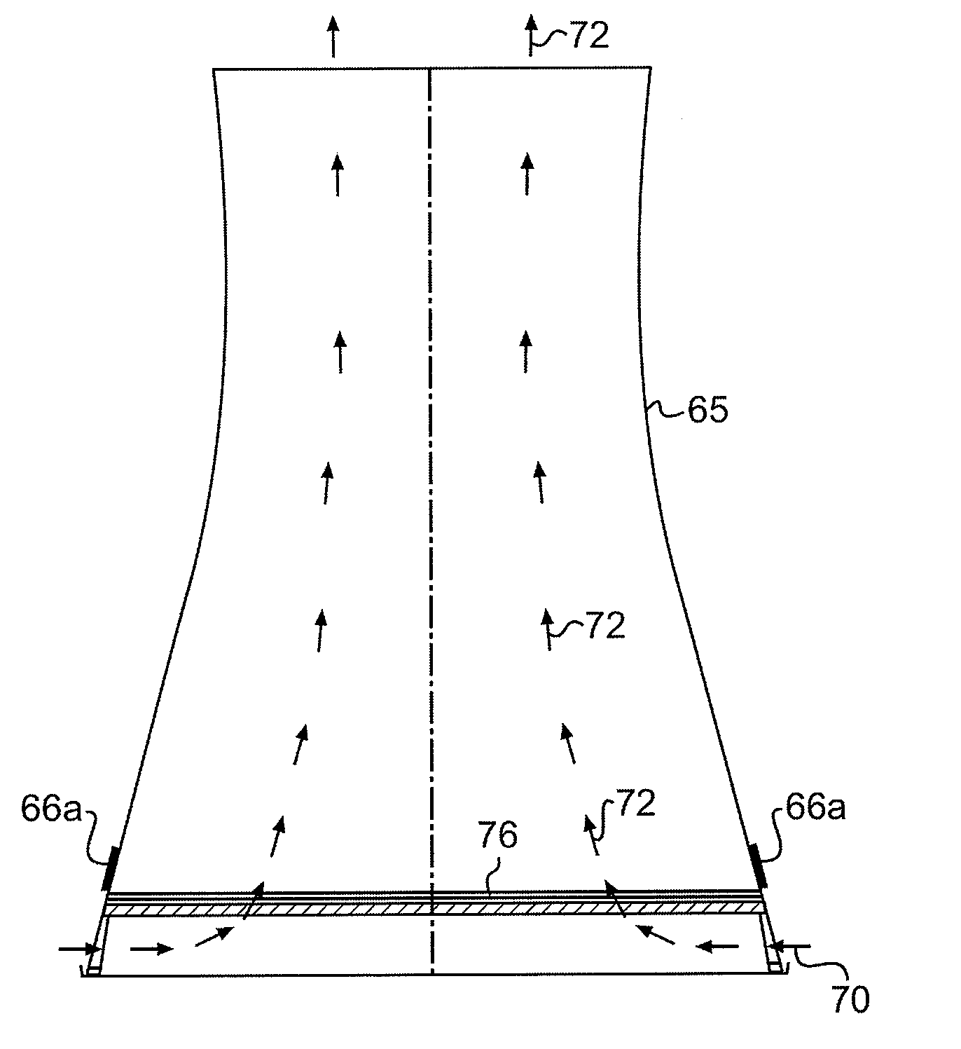
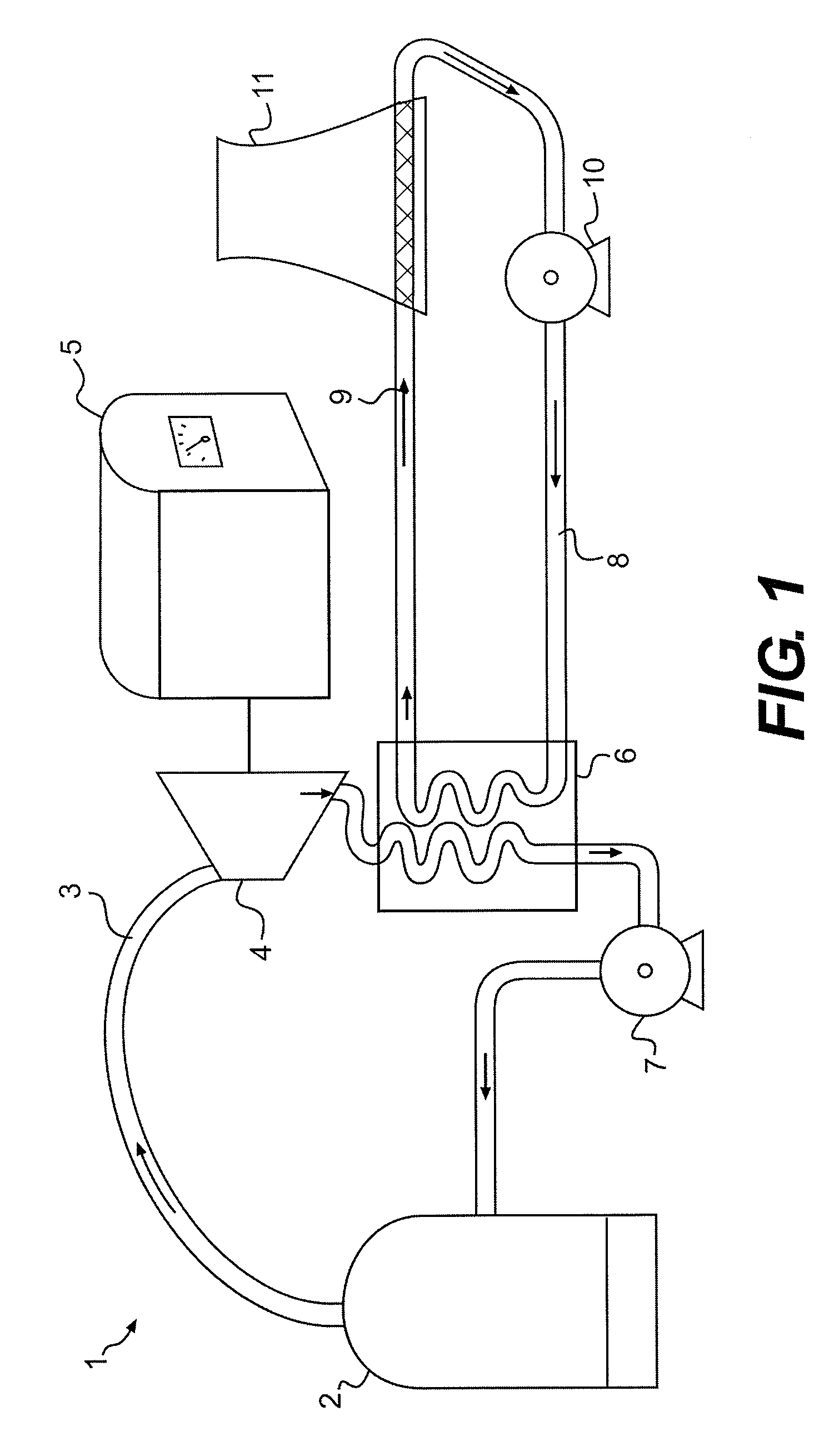
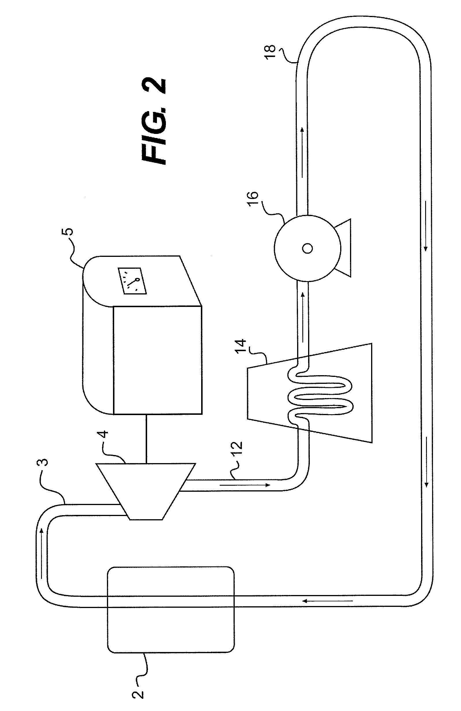
[0040]FIG. 1 is a schematic diagram of the steam / water circuit 1 of a greatly-simplified electric power generating installation. A boil...


PUM


Abstract

The present invention relates to a natural draft cooling tower that employs an air cooled condenser. The aforementioned cooling tower operates by natural draft and achieves the exchange of heat between two fluids such as atmospheric air, ordinarily, and another fluid which is usually steam. The aforementioned cooling tower utilizes a central steam duct riser supplying steam to perimeter ducting via radial ducting.

Description

FIELD OF THE INVENTION[0001]The present invention relates to a natural draft cooling tower that employs an air cooled condenser. The aforementioned cooling tower operates by natural draft and achieves the exchange of heat between two fluids such as atmospheric air, ordinarily, and another fluid which is usually steam. The aforementioned cooling tower operates by natural draft which utilizes buoyancy via a tall chimney. Warm, air naturally rises due to the density differential to the cooler outside ambient air. Warm air is indeed obviously less dense than colder ambient air at the same pressure.BACKGROUND OF THE INVENTION[0002]Cooling towers are heat exchangers of a type widely used to emanate low grade heat to the atmosphere and are typically utilized in electricity generation, air conditioning installations and the like. In a natural draft cooling tower for the aforementioned applications, airflow is induced via hollow chimney-like tower by the density difference between cool air e...

Claims


Application Information

Patent Timeline
Patent Type & Authority Patents(United States)
IPC IPC(8): F01K13/00F24H3/00
CPCF28B1/06F28D1/04
Inventor BADIN, FRANCISTHIRY, BENOITCORNELIS, MARCVOUCHE, MICHEL
Owner SPG DRY COOLING USA LLC
Learn More