Method of producing a composite component

a composite component and manufacturing method technology, applied in lamination, domestic applications, chemistry apparatus and processes, etc., can solve the problems of increasing the flow limit of the hollow section material, inability to produce a positive lock providing sufficient holding, and insufficient fixation of the two components relative to each other, so as to improve the material quality and the adhesion of the composite. , the effect of improving the internal high pressure of the hollow section

Active Publication Date: 2016-07-12
DAIMLER AG
View PDF14 Cites 0 Cited by
  • Summary
  • Abstract
  • Description
  • Claims
  • Application Information

AI Technical Summary

Benefits of technology

[0004]Exemplary embodiments of the present invention provide a method of producing a composite component that improves the composite adhesion in a composite component consisting of a hollow section which is expanded by internal high pressure and a plastics material portion.
[0013]Preferably, when carrying out the method, a hollow section made from a deformable non-ferrous metal, preferably aluminum or an aluminum base alloy, is used. Precisely when using aluminum or aluminum base alloys, the aforementioned effects on the deformability due to temperature, shear stresses and back-pressure become particularly clearly noticeable, so that even with aluminum, which per se has low elastic limits, considerably greater degrees of deformation and hence a better positive lock between the hollow section and the plastics material portion can be achieved. Upon expanding the hollow section, in this case a maximum increase in diameter of 10% to 15% and in particular of 15% to 35% is achieved. This very considerably exceeds the degrees of deformation of 12% to 15% which are conventional for aluminum, so that even large undercuts between the metal and the plastics material portion can be achieved.

Problems solved by technology

The fixing of the two components relative to each other is, however, often inadequate despite these measures.
Particularly in the case of hybrid components connected in positive manner, it is often not possible to produce a positive lock providing sufficient holding.
At the same time, owing to the temperature of the injection molding compound and the shear stresses acting on the hollow section during the third step due to the pasty or liquid injection molding compound, which result in an increase in the flow limit of the hollow section material, particularly high degrees of deformation can be achieved.

Method used


Image

  • Method of producing a composite component
  • Method of producing a composite component
  • Method of producing a composite component

Examples


Embodiment Construction

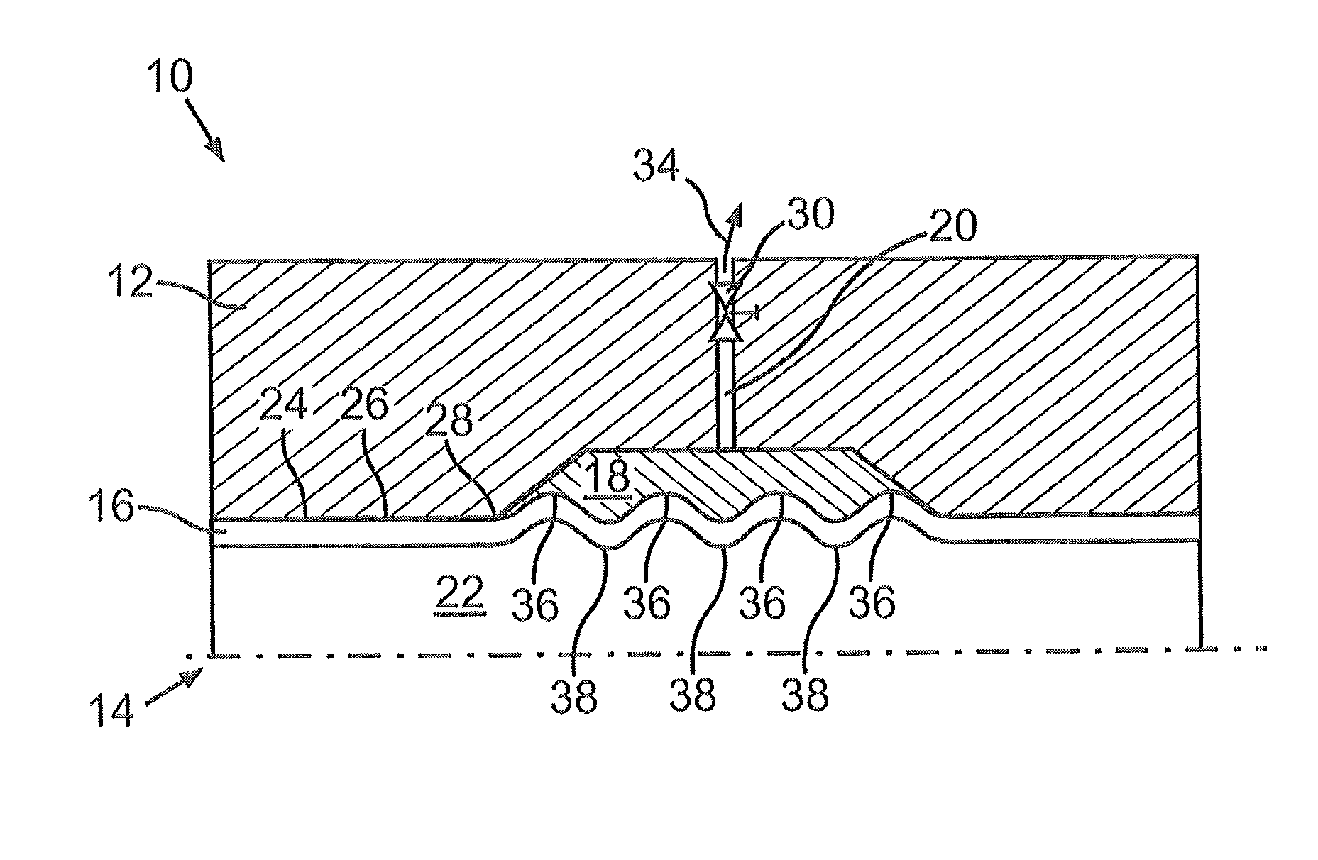
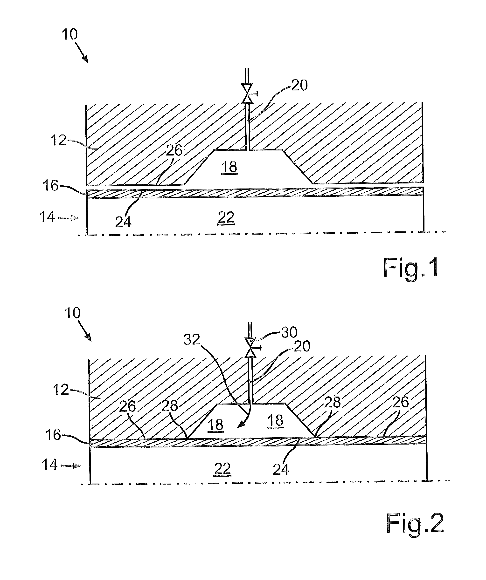
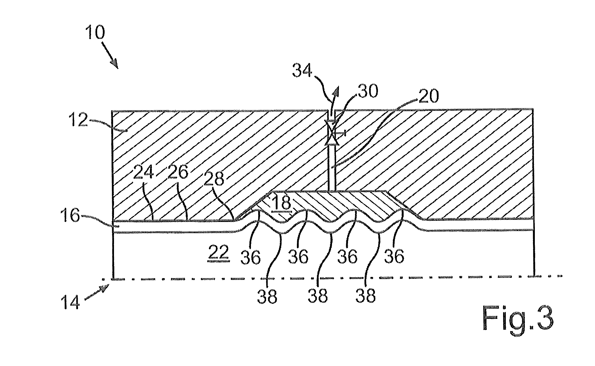
[0018]A combined injection molding and hydroforming mold, referenced 10 overall, of which one half of the mold partial region 12 is illustrated in FIG. 1, comprises a central cavity 14 for receiving a hollow section 16 and also a sprue cavity 18 into which an injection molding compound, in particular a plastics material, can be fed through a sprue line 20.

[0019]FIG. 1 shows the mold 10 with the hollow section 16 prior to carrying out the method. To produce the composite component, initially the inner void 22 of the hollow section 16 is acted upon by a pressure, which expands the hollow section 16, until the outer wall 24 thereof comes to lie against the wall 26 of the cavity 14 of the mold 10, and optionally also expands slightly into the mold region 18.

[0020]In particular, this, as can be seen in FIG. 2, brings the edge region 28 of the sprue cavity 18 into contact with the outer wall 24 of the hollow section 16. As soon as the outer wall 24 has come to lie against the edge region ...


PUM

PropertyMeasurementUnit
temperatureaaaaaaaaaa

Abstract

A method of producing a composite component, in which a hollow section is expanded, at least in regions, by internal high pressure. In a first step a region of the hollow section is expanded until it comes to lie against an edge region of a cavity of a combined hydroforming and injection mold. In a second step the cavity is filled with an injection molding compound. In a third step the hollow section, at least in regions, is expanded further, which increases the internal high pressure.

Description

BACKGROUND AND SUMMARY OF THE INVENTION[0001]The invention relates to a method of producing a composite component.[0002]PCT International Publication No. WO 2008 / 125233 A1 discloses a method of producing a composite component in which a hollow section is expanded by internal high pressure and is simultaneously encapsulated with plastics material in a bulge region. The simultaneous expansion and encapsulation is intended to produce an improved positive lock.[0003]With polymer hybrid components that are known per se, which are designed as a combination of an injection molded component and a hydroformed metal component, the composite adhesion between the two component parts of the component is brought about by an adhesion promoter or by a positive lock between the two components. The fixing of the two components relative to each other is, however, often inadequate despite these measures. Particularly in the case of hybrid components connected in positive manner, it is often not possibl...

Claims


Application Information

Patent Timeline
Patent Type & Authority Patents(United States)
IPC IPC(8): B29C45/14B29L31/30
CPCB29C45/1418B29C2045/14213B29L2031/3002
Inventor DUDZIAK, KAI-UWEFALKE, JUERGENREESE, ECKHARD
Owner DAIMLER AG
Why Eureka
Try Eureka