Overload clutch

a technology of overloading and clutch, applied in the field of overloading clutch, can solve the problems of inadmissible stresses and overly intense shrinkage behavior of the encompassing ring, and achieve the effects of increasing the mechanical characteristics of injection-moulded parts, reducing shrinkage, and increasing the peripheral accommodation of load

Active Publication Date: 2020-06-16
OECHSLER AG
View PDF5 Cites 0 Cited by
  • Summary
  • Abstract
  • Description
  • Claims
  • Application Information

AI Technical Summary

Benefits of technology

[0008]Thus, the elastic enclosure of the ribbed disc by the encompassing ring leads, as a result of a reversible transition between adhesive (static) friction and positive locking, to a defined, reproducible reaction of the clutch to overload. After the depletion of said overload, the torque that is introduced is again transmitted without losses.
[0010]The axial height of the ribs which run in radial fashion on both sides of the ribbed disc expediently decreases in the direction of the U yoke of the encompassing ring, because the two encompassing limbs are connected to one another by means of the U yoke, that is to say cannot move apart from one another. Along the ring-shaped U yoke, the ribs run into the planes of the axial side surfaces of the ribbed disc. In the ring region inside the outer edge of the ribbed disc, the clutch thus exhibits virtually no positive locking, but rather practically only adhesive (static friction) engagement, with the stiff elastic encompassing action of the encompassing ring shrunk onto the ribbed disc. If said adhesive (static friction) engagement exhibits the tendency to transition to sliding engagement in reaction to the introduced torque, the axial engagement of the ribs against the U limbs of the encompassing ring immediately begins to bear load. The rib heights which increase proceeding from the U yoke result in an increasing peripheral accommodation of load, with the U-limbs being spread apart. If a further increasing torque then causes the ribs to be lifted axially out of mutual engagement along their flanks, with the free U limbs of the encompassing ring being deflected axially away from one another, this results in spinning in the manner of a ratchet; this occurs until the torque falls again and, with the engagement of the flanks of the ribs into one another, the adhesive (static friction) engagement between ribbed disc and encompassing ring re-stabilizes.
[0011]This results in an increased combined clutch action, which arises from the adhesive (static) friction between the mutually abutting surfaces of the ribbed disc, which is encapsulated by the encompassing ring, and the radially increasing, rib-like positive locking between said surfaces. Owing to the structurally predefinable gradient and peripheral rounding of the rib flanks on the ribbed disc, the onset of the transition from pure sliding friction to the mixed adhesive (static friction) engagement and positive locking can be influenced; also, by means of asymmetrical flanks of the ribs on the two sides of the ribbed disc, the clutch force can be made dependent on the direction of rotation. By injection of a lubricant between the hub ring and encompassing ring, for example through a thin duct left free during the encapsulation process, the torque that can be transmitted by the clutch can be reduced in targeted fashion.
[0012]By means of an axial and radial widening, which can likewise be structurally predefined, of the ribs which thus run in each case in the manner of a T-shaped tongue into the surface of the ribbed disc, it is the case here that critical specific material loads along the periphery of the ribbed disc owing to the axial contact pressure imparted by the shrunk-on encompassing ring are avoided. In this way, a broader spectrum of plastics can be used for the ribbed disc. Furthermore, such a geometry opens up a further degree of freedom for the structural influencing of the reaction behaviour of the clutch.
[0013]The overload clutch can advantageously be standardized even for relatively low torques. It is furthermore suitable for transmitting high torques in a restricted structural space. For the transmission of even higher loads, said clutch can be easily cascaded axially along a central shaft.

Problems solved by technology

In particular, it would otherwise be possible for overly intense shrinkage behaviour of the encompassing ring to lead to inadmissible stresses, to the point of material deformations, in the ribbed disc which is encompassed in ring-shaped encircling fashion by the encompassing ring.

Method used


Image

  • Overload clutch
  • Overload clutch
  • Overload clutch

Examples


Embodiment Construction

[0021]Hereinafter, embodiments according to the present disclosure will be described with reference to the accompanying drawings.

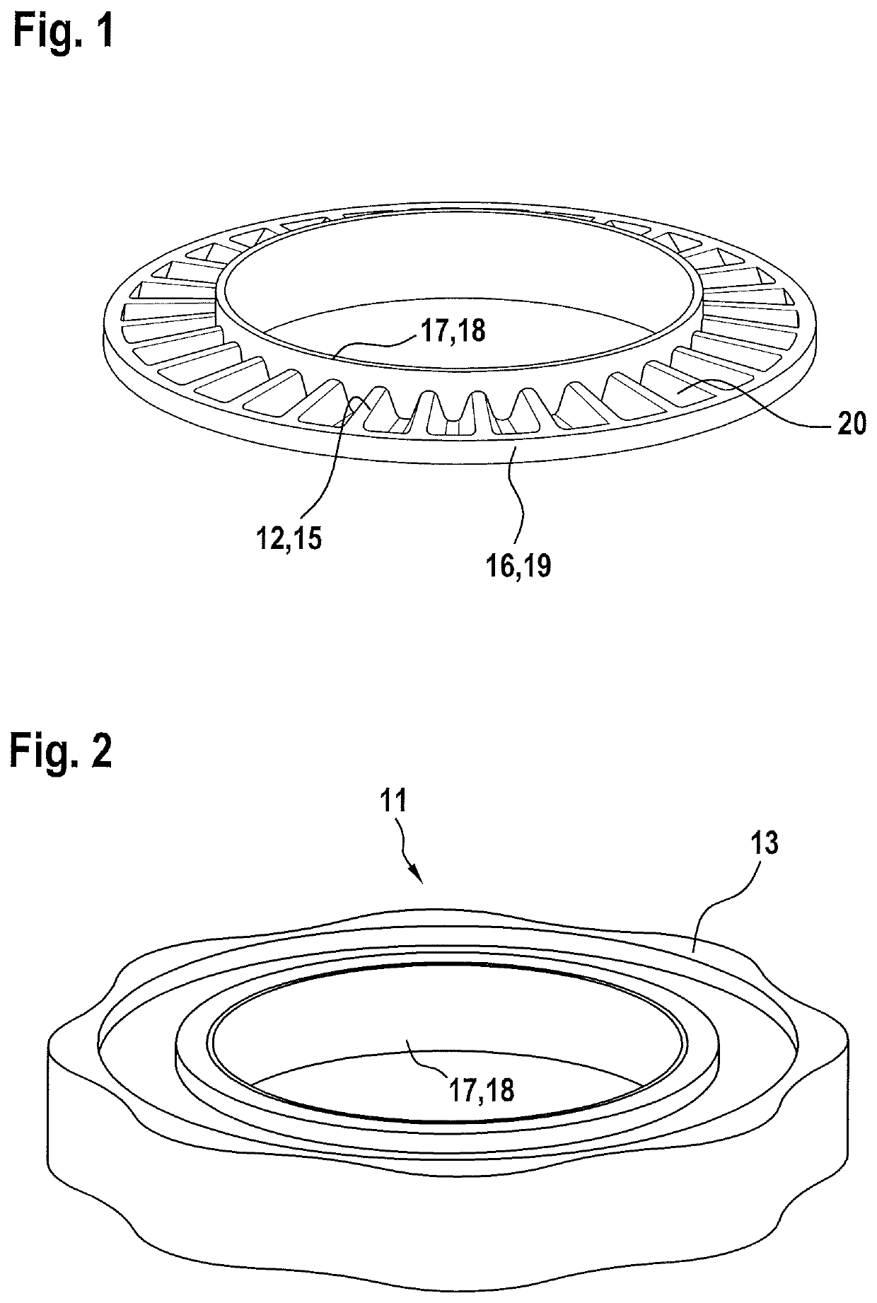
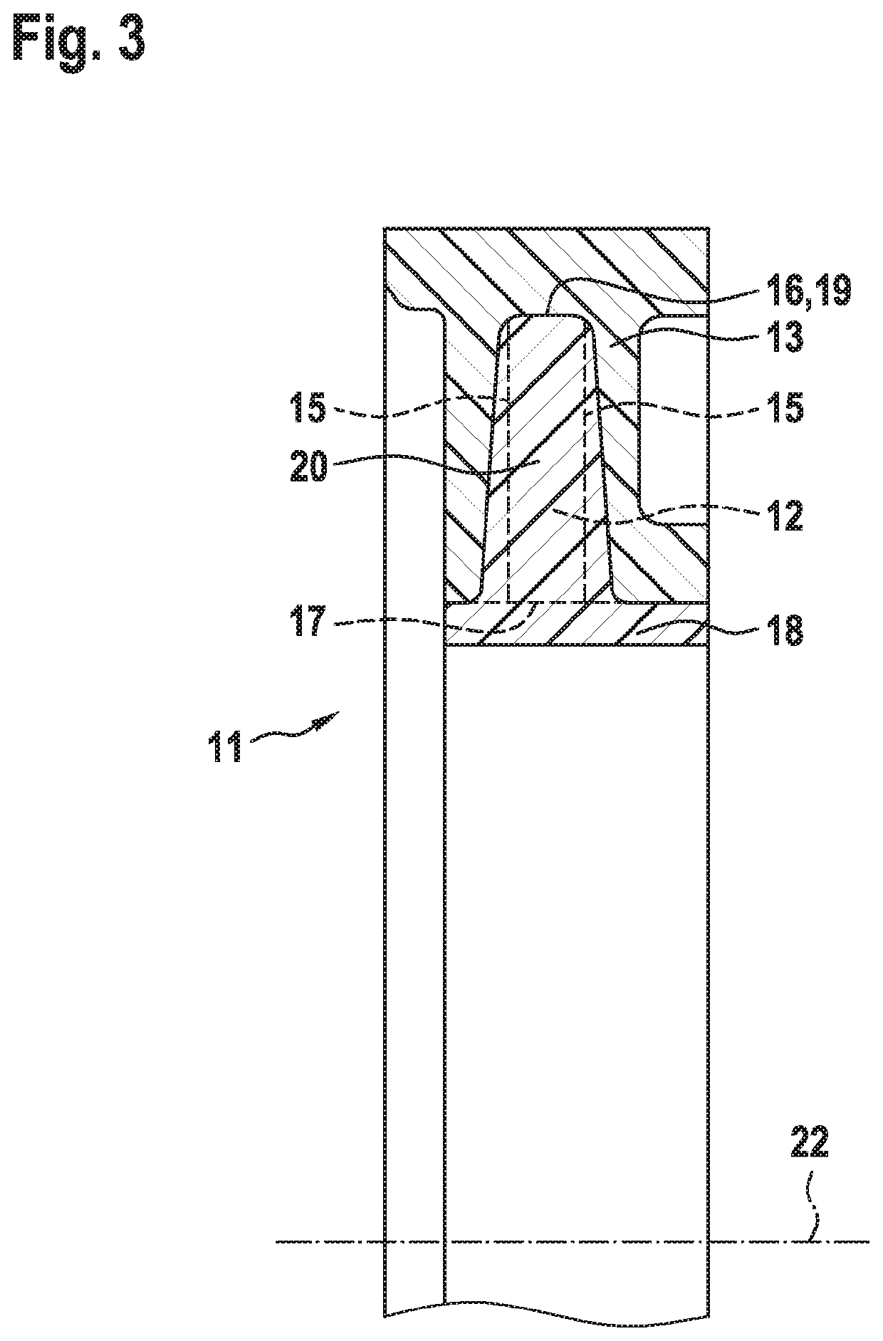
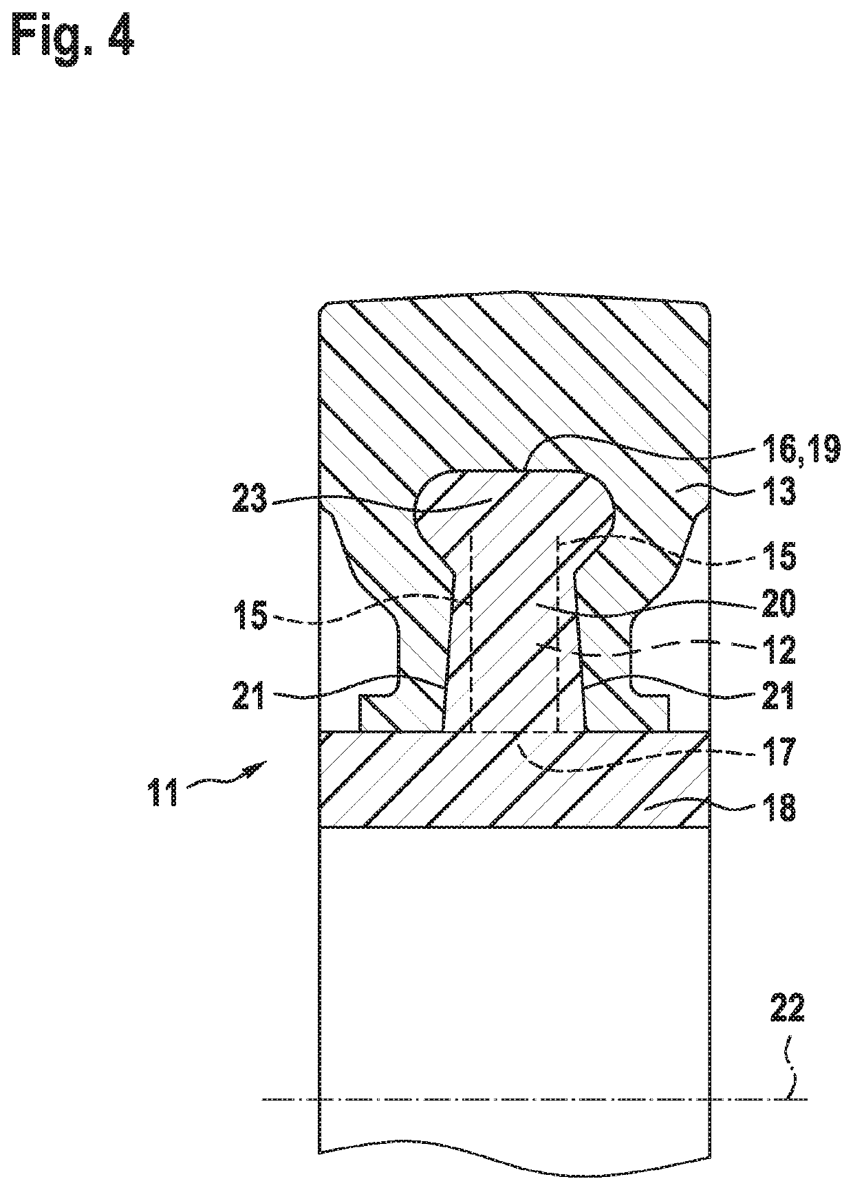
[0022]The clutch 11, which reacts reversibly and reproducibly to a predefined torque or generally to torque overload, has a substantially planar ribbed disc 12 which is produced by plastics injection moulding and which has a central hole. Said ribbed disc is, as per FIG. 3, encompassed in U-shaped fashion in axial longitudinal section, likewise by plastics injection moulding, by an encompassing ring 13, specifically is surrounded by a plastic on both of its axial side surfaces 15 and on its face 16 which runs in encircling fashion along the outer periphery 19, which plastic, as a result of intense shrinkage phenomena during the cooling process, enters into adhesive (static friction) engagement with the ribbed disc 12. The ribbed disc 12 thus acts as a hub for this rotating assembly.

[0023]Onto the inner periphery 17 of the ribbed disc 12 there is integrally...


PUM

PropertyMeasurementUnit
torqueaaaaaaaaaa
static frictionaaaaaaaaaa
heightsaaaaaaaaaa

Abstract

A clutch which reacts to torque overload has a ribbed disc which is produced by plastics injection moulding and which is, along its inner or outer periphery, encapsulated in encircling fashion and on both axial side surfaces by an encompassing ring. Said encompassing ring, owing to shrinkage as a result of cooling, enters into static friction engagement with the ribbed disc, and furthermore engages, by means of bevelled flanks, with ribs running radially on at least one of the side surfaces of the ribbed disc.

Description

CROSS-REFERENCES TO RELATED APPLICATIONS[0001]This application claims the benefit of German Application No. DE102017004617.4 filed May 13, 2017 and German Application No. DE102016012293.5 filed Oct. 16, 2016, the entire content of each of which is incorporated herein by reference.TECHNICAL FIELD[0002]The invention relates to an overload clutch.BACKGROUND ART[0003]A clutch of said type is known from U.S. Pat. No. 3,186,190 for the transmission of torque, in a manner protected against overloading, in a motor drivetrain. There, at the end of a shaft, the shell surface of a cylindrical metallic hub is encapsulated by a ring composed of plastic. The hub and ring are connected to one another exclusively by adhesive (static friction) action. This coupling turns to sliding friction if the rotational movement of the hub relative to the ring is braked to a critical degree. Owing to the selected material pairing, it is then the case that, under the influence of the heat of friction that arises...

Claims


Application Information

Patent Timeline
Patent Type & Authority Patents(United States)
IPC IPC(8): F16D7/02F16D7/00F16D1/072F16D1/096B29C45/14B29L31/00
CPCF16D7/021F16D1/096F16D1/072F16D7/022F16D7/024F16D7/002Y10T403/559B29C45/14819B29L2031/7486F16D43/211F16D43/213
Inventor LIERET, ROLANDWOLF, MARTIN
Owner OECHSLER AG
Why Eureka
Try Eureka