Advection fans

a technology of axial fans and air currents, applied in the direction of positive displacement liquid engines, liquid fuel engines, pumping pumps, etc., can solve the problems of not being able to reduce axial fans cannot guide air currents in the radial direction, and the overall axial height of electronic products cannot be reduced. , to achieve the effect of increasing air output and wind pressure, and reducing unnecessary nois

Inactive Publication Date: 2015-09-22
SUNONWEALTH ELECTRIC MACHINE IND
View PDF16 Cites 7 Cited by
  • Summary
  • Abstract
  • Description
  • Claims
  • Application Information

AI Technical Summary

Benefits of technology

[0010]An objective of the present invention is to provide an advection fan in which the stator does not occupy much space of the advection fan, effectively increasing the air output and the wind pressure while reducing unnecessary noise.
[0011]Another objective of the present invention is to provide an advection fan that includes a housing having a reduced axial height, allowing development and research in miniaturization.
[0012]A further objective of the present invention is to provide an advection fan including an impeller that guides air currents in and out in a radial direction to reduce hindrance to the air currents by the stator, increasing the cooling effect.

Problems solved by technology

However, axial fans can only guide air currents to flow in the axial direction for cooling purposes.
Namely, axial fans can not guide air currents to flow in the radial direction.
Thus, the axial fans must be mounted on top of a heat source (such as on a top face of a central processing unit of a personal computer) when used in various electronic products, such that the overall axial height of the electronic products can not be reduced.
As a result, the blower fans are not suitable for electronic products (such as cell phones, personal digital assistants, etc,) that must guide the air currents in lateral direction into a lateral side of the electronic product.
Namely, axial fans and blower fans currently available in the market can not be applied in small electronic products having limited inner spaces.
The air guiding space in the miniaturized housing 91 is insufficient for guiding air currents, leading to a significant decrease in the air output and the wind pressure.
Thus, the air currents are hindered by a large portion of the hub while flowing through the passage 911, causing turbulence and resulting in considerable insufficiency in the air output and the wind pressure, significantly and adversely affecting the overall cooling effect of the advection fan 9.

Method used


Image

  • Advection fans
  • Advection fans
  • Advection fans

Examples


first embodiment

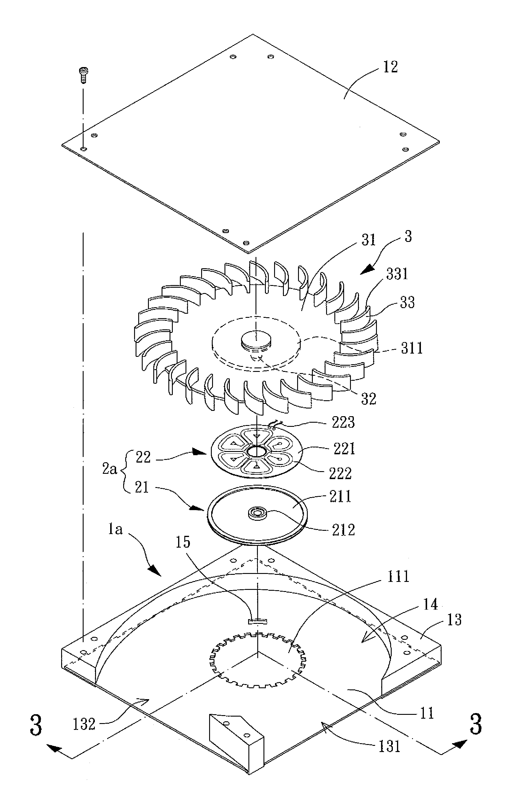
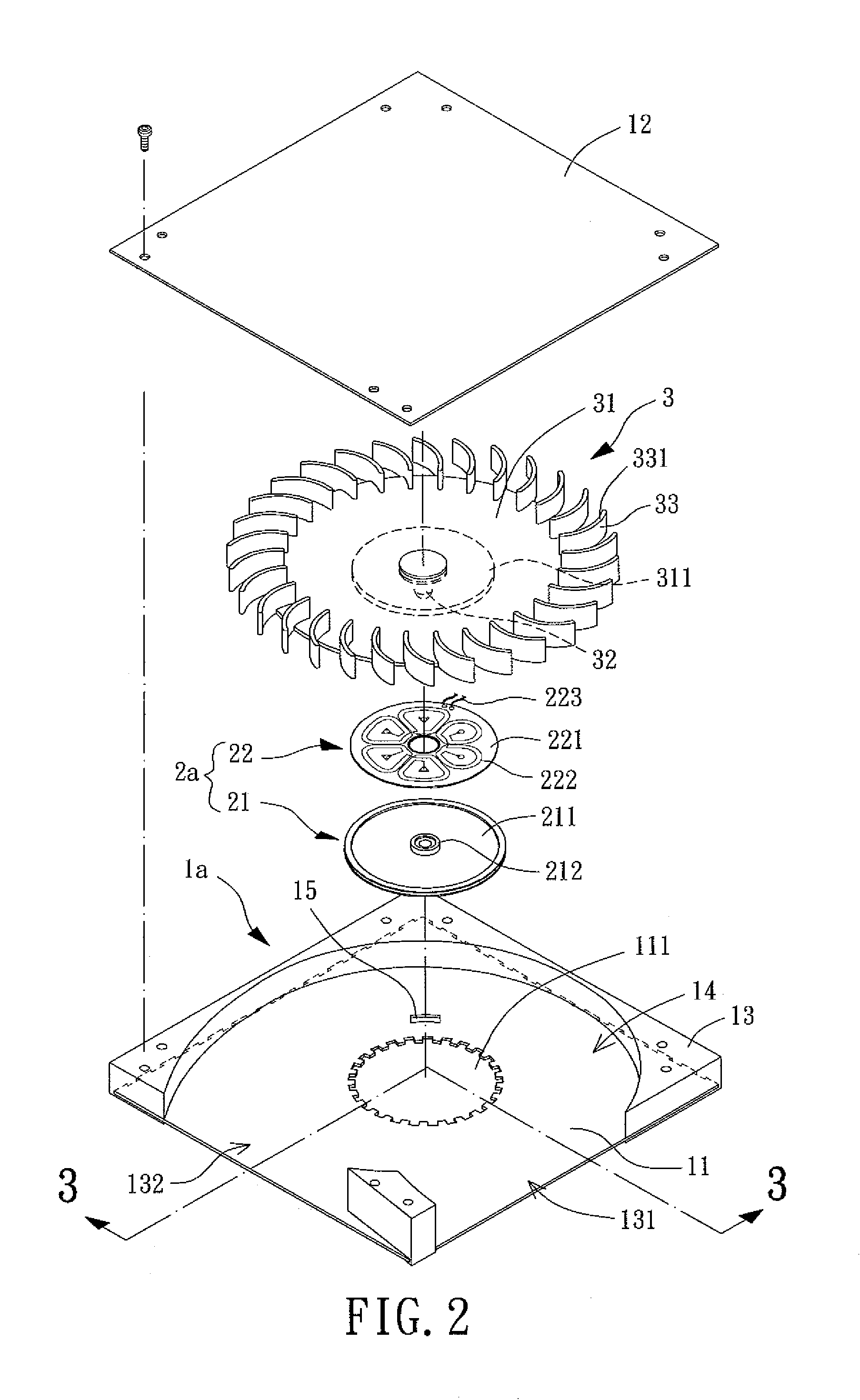
[0041]An advection fan of a first embodiment according to the present invention is shown in FIGS. 2 and 3 and includes a housing 1a, a stator 2a, and an impeller 3. The housing 1a is configured to allow air currents to flow in a radial direction. The stator 2a is mounted to the housing 1a. The impeller 3 is rotatably coupled to the stator 2a and can be driven by the stator 2a to rotate.

[0042]The housing 1a can be any hollow frame that receives the stator 2a and the impeller 3 and that guides air currents in and out in the radial direction. The housing 1a can be of any geometric shape, such as polygonal, cylindrical, or elliptic. In this embodiment, the housing 1a is rectangular in a top view thereof.

[0043]The housing 1a includes a metal housing base 11 and a closure member 12 spaced from the metal housing base 11 in an axial direction. A lateral wall 13 is provided between the metal housing base 11 and the closure member 12 and includes an air inlet 131 and an air outlet 132 spaced ...

second embodiment

[0050]FIGS. 4 and 5 show an advection fan of a second embodiment according to the present invention. Similar to the first embodiment, the second embodiment includes a housing 1b, a stator 2b, and an impeller 3. The housing 1b is substantially the same as the housing 1a and includes a metal housing base 11, a closure member 12, a lateral wall 13, an air inlet 131, an air outlet 132, an air passage 14, and a wire hole 15. The structural features of the housing 1b and the impeller 3 of the second embodiment identical to those of the housing 1a and the impeller 3 will not be described in detail to avoid redundancy.

[0051]The difference between the housing 1b of the second embodiment and the housing 1a of the first embodiment is that the engagement section of the metal housing base 11 of the housing 1b for coupling with the stator 2b (by embedding or abutment / attachment) is in the form of a recess 112 formed in the surface of the metal housing base 11 by punching. The recess 112 includes ...

third embodiment

[0057]FIGS. 9 and 10 show an advection fan of a third embodiment according to the present invention. Similar to the first embodiment, the third embodiment includes a housing 1c, a stator 2c, and an impeller 3. The housing 1c is substantially the same as the housing 1a and includes a metal housing base 11, a closure member 12, a lateral wall 13, an air inlet 131, an air outlet 132, and an air passage 14. The structural features of the housing 1c and the impeller 3 of the third embodiment identical to those of the housing 1a and the impeller 3 will not be described in detail to avoid redundancy.

[0058]The difference between the housing 1c of the third embodiment and the housing 1a of the first embodiment is that the engagement section of the metal housing base 11 of the housing 1c for coupling with the stator 2c by abutment / attachment includes a shaft receiving hole 113 and an engagement face 1131 surrounding the shaft receiving hole 113. Preferably, the engagement face 1131 correspond...


PUM


Abstract

An advection fan includes a housing having a metal housing base and a closure member. A lateral wall is arranged between the metal housing base and the closure member and includes an air inlet and an air outlet. A horizontal air passage is defined between the metal housing base and the closure member. The metal housing base includes an engagement section. A stator includes a coil unit embedded in or abutting and attached to the engagement section of the metal housing base. The coil unit abuts the engagement face of the metal housing base. The coil unit includes a substrate and at least one coil formed on a surface of the substrate by a printing circuit or electroforming process. An impeller is rotatably coupled to the shaft tube of the stator. A gap is formed between the impeller and the coil unit of the stator.

Description

BACKGROUND OF THE INVENTION[0001]1. Field of the Invention[0002]The present invention relates to advection fans and, more particularly, to advection fans that allow air currents to enter and exit in a direction perpendicular to an axial direction.[0003]2. Description of the Related Art[0004]Conventional cooling fans generally include axial fans and blower fans. An axial fan generally includes an axial air inlet and an axial air outlet spaced in an axial direction. Air currents are guided into the axial air inlet and then exit from the axial air outlet to provide a cooling function. A blower fan generally includes an axial air inlet and a radial air outlet. Air currents are guided into the axial air inlet and then exit from the radial air outlet to provide the cooling function.[0005]However, axial fans can only guide air currents to flow in the axial direction for cooling purposes. Namely, axial fans can not guide air currents to flow in the radial direction. Thus, the axial fans mus...

Claims


Application Information

Patent Timeline
Patent Type & Authority Patents(United States)
IPC IPC(8): F04D25/06F04D17/04F04D29/42F04D29/40F04D29/60
CPCF04D17/04F04D25/0653F04D29/4226F04D25/06F04D25/064F04D25/0606F04D25/0646F04D29/403F04D29/602
Inventor HORNG, ALEX
Owner SUNONWEALTH ELECTRIC MACHINE IND
Why Eureka
Try Eureka