Oil scraper ring for pistons of internal combustion engines

An oil scraping ring, internal combustion engine technology, applied in the direction of piston rings, mechanical equipment, engine components, etc., can solve the problems of improving fuel consumption, wear, and reducing the efficiency of internal combustion engines, and achieves efficiency improvement, wear reduction, and oil scraping performance. Effect

Inactive Publication Date: 2006-10-25
MAHLE GMBH
View PDF2 Cites 7 Cited by
  • Summary
  • Abstract
  • Description
  • Claims
  • Application Information

AI Technical Summary

Problems solved by technology

However this creates a high surface pressure on the working face of the disc, which leads to high wear when the engine is running
This wear reduces the efficiency of the internal combustion engine, resulting in increased fuel consumption

Method used


Image

  • Oil scraper ring for pistons of internal combustion engines
  • Oil scraper ring for pistons of internal combustion engines

Examples


Embodiment Construction

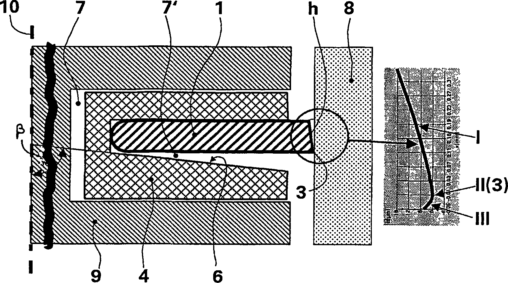
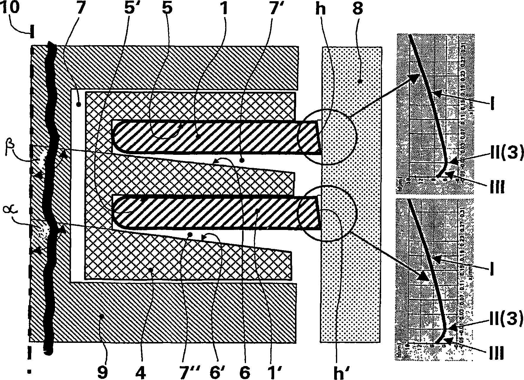
[0027] Such as figure 1 It can be seen that an oil wiper ring consists of a disk 1 and an expansion spring 4 which presses the disk radially against a cylinder wall 8 . Expansion spring 4 is installed in an annular groove 7, and this annular groove has two sides that become 90 degrees with piston shaft 10, and this expansion spring has the shape and size corresponding to annular groove. The expansion spring has a spring groove 7' which has a spring groove side 5 representing the side facing the top of the piston and a spring groove side 6 representing the side facing away from the top of the piston. According to the invention, the spring groove side 5 facing the piston crown is arranged at 90° to the piston shaft 10, wherein the spring groove flank 6 facing away from the piston crown extends obliquely at an angle β away from the piston crown to the spring outer circumference. Preferably, the angle β is 85° to 87°.

[0028] According to the invention, the disk 1 has a crown-s...


PUM


Abstract

The invention relates to an oil scraper ring for pistons of internal combustion engines, said oil scraper ring comprising a disc (1) that is provided with parallel flanks and a bearing surface (h) having an asymmetrical crowned form with a vertex line (3) extending over the periphery of the disc. A bracing spring (4) arranged in a ring groove (7) of the piston and comprising a spring groove side (6) opposing the piston head and a spring groove side (5) facing the piston head presses the disc (1) radially against the cylinder wall (8). The aim of the invention is to achieve an improved oil scraping action compared to that of prior art, while reducing the friction and the abrasion of the bearing surface. To this end, at least one of the spring groove sides (5, 6) extends at an angle (ss) in relation to the piston axis (10) in such a way that it is radially outwardly inclined to the bracing spring end oriented towards the cylinder, the bearing surface (h) of the disc (1) being embodied in such a way that it corresponds to an almost worn end contour in the started engine state, and, when the oil scraper ring (1) is mounted in the piston, the vertex line (3) of the bearing surface (h) is oriented in the direction of the ring groove side (6) opposing the piston head.

Description

technical field [0001] The invention relates to an oil wiper ring for a piston of an internal combustion engine, which comprises a disk made of steel strips with parallel sides, the running surface of which has a crown-shaped asymmetrical shape comprising a The apex line extending around the periphery of the disc, where the disc is pressed against the cylinder wall by an expansion spring arranged in a ring groove of the piston, the expansion spring having a spring groove side facing away from the top side of the piston and a side facing the top side of the piston side of the reed slot. Background technique [0002] Excessive engine oil reaching the combustion chamber, in addition to high fuel consumption, can also have a negative impact on the engine's emissions performance. In order to prevent this phenomenon, a sufficient tangential force of the oil wiper ring for generating a radial contact pressure on the cylinder wall, and thus a good oil scraping action, is indispensa...

Claims


Application Information

Patent Timeline
Patent Type & Authority Applications(China)
IPC IPC(8): F16J9/06F16J9/20
CPCF16J9/065F16J9/206F16J9/06F16J9/12
Inventor 罗尔夫-格哈德·菲德勒
Owner MAHLE GMBH
Why Eureka
Try Eureka