Ceiling Fan Motor

a ceiling fan and motor technology, applied in the direction of magnetic circuit rotating parts, lighting support devices, magnetic circuit shapes/forms/construction, etc., can solve the problems of not being suitable for ceiling fans and disturbed space planning, and achieve the effect of improving the utility of ceiling fan motors

Active Publication Date: 2016-12-01
SUNONWEALTH ELECTRIC MACHINE IND
View PDF6 Cites 5 Cited by
  • Summary
  • Abstract
  • Description
  • Claims
  • Application Information

AI Technical Summary

Benefits of technology

[0023]Based on the above structures, since the light-emitting module in the individual embodiments of the disclosure is arranged either between the iron core and the shaft or between the iron core and the housing of the rotor along the radial direction, it is possible to align the light-emitting module with the rotor or the iron core. As such, arrangement of the light-emitting module will not increase the axial height of the ceiling fan motor, thereby improving the utility of the ceiling fan motor.

Problems solved by technology

Disadvantageously, space planning is disturbed.
Since the ceiling fan 9 is generally mounted to the ceiling of a building, it will not be suitable to install the ceiling fan 9 in a room with a low ceiling.

Method used


Image

  • Ceiling Fan Motor
  • Ceiling Fan Motor
  • Ceiling Fan Motor

Examples


first embodiment

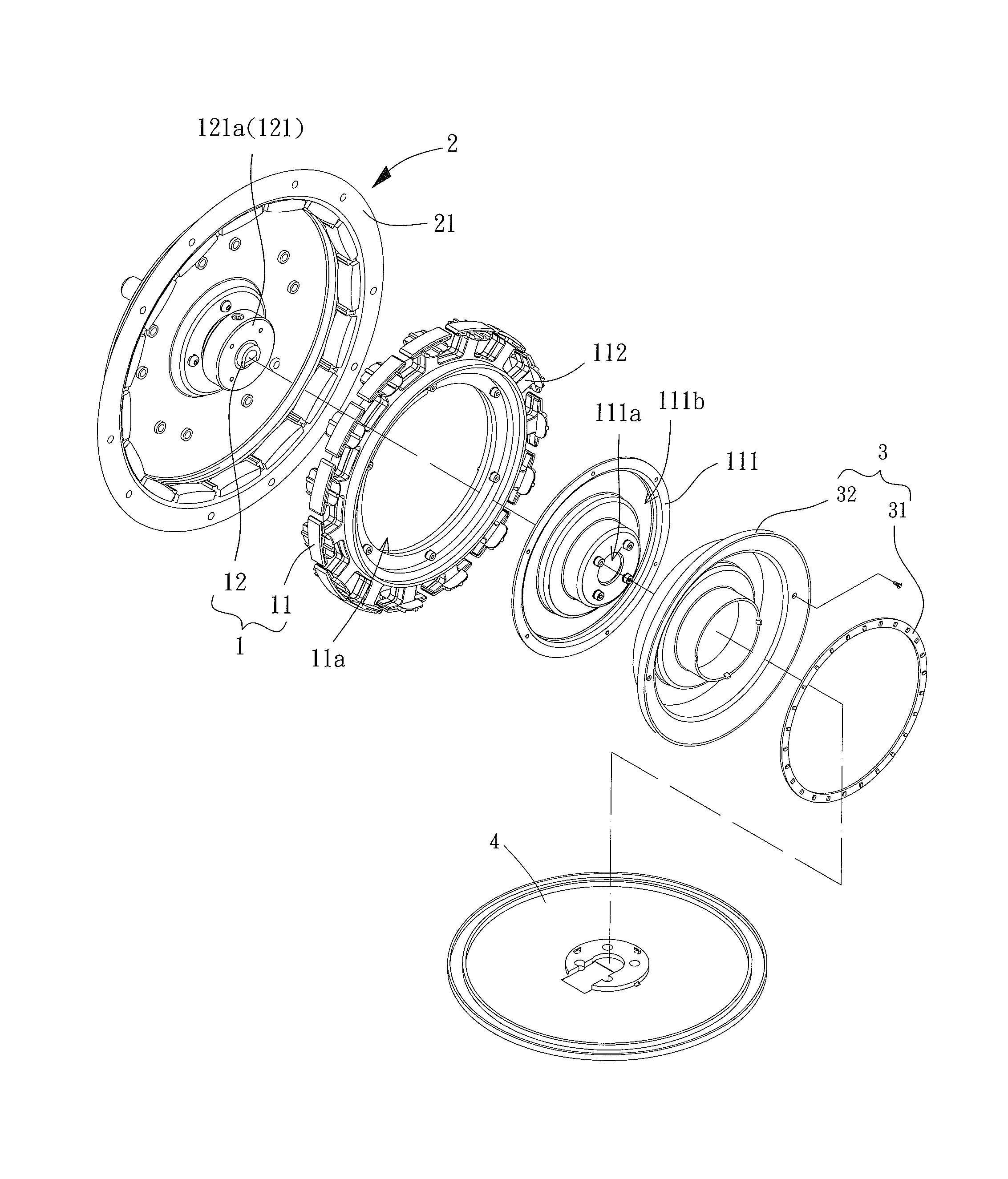
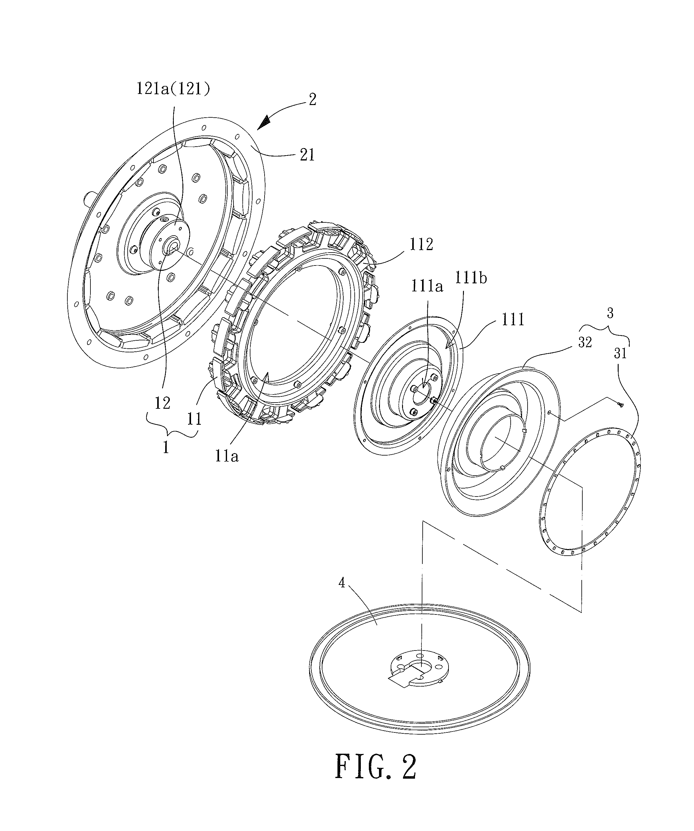
[0037]FIGS. 2 and 3 show a ceiling fan motor having a light-emitting module according to the disclosure. The ceiling fan motor includes a stator 1, a rotor 2 and a light-emitting module 3. The rotor 2 is rotatably coupled with the stator 1. The stator 1 includes an iron core 11 and a shaft 12. The light-emitting module 3 is at least partially arranged between the iron core 11 and the shaft 12.

[0038]The iron core 11 may be in the form of a plurality of stacked silicon steel plates, or in the form of an integrally-formed monolithic piece made of a magnetically conductive material. The iron core 11 includes an assembly opening 11a at the central portion thereof. The shaft 12 may extend into the assembly opening 11a. The iron core 11 may couple with the shaft 12. In the embodiment, the iron core 11 is connected to a base 111 which is located in the assembly opening 11a. The base 111 has a shaft hole 111a at the center thereof. The shaft 12 extends through the shaft hole 111a. The shaft ...

fourth embodiment

[0055]Based on the above structure, the light-emitting module 3 is arranged at least partially between the iron core 11 and the housing 21 along the radial direction perpendicular to the shaft 12 in the As such, the light-emitting module 3 can be at least partially aligned with the rotor 2 or the iron core 11 along the radial direction perpendicular to the shaft 12. In this manner, arrangement of the light-emitting module 3 will also not increase the axial height of the ceiling fan motor.

[0056]Besides, the embodiment also includes a lampshade 4. However, the lampshade 4 is coupled with the stator 1. Since the light-emitting module 3 is arranged between the iron core 11 and the housing 21, the lampshade 4 can also be thin and be in a flat form along the radial direction perpendicular to the shaft 12. According to the discussed embodiments of the disclosure, the lampshade 4 may couple with the lamp seat 32 of the light-emitting module 3 or the stator 1.

[0057]Referring to FIGS. 8 and ...


PUM


Abstract

A ceiling fan motor with a reduced axial height includes a stator, a rotor and a light-emitting module. The stator includes an iron core and a shaft. The iron core forms an assembly opening at a central portion thereof. The rotor is rotatably coupled with an outer periphery of the shaft and includes a housing. The light-emitting module is at least partially arranged between the iron core and the shaft, or is arranged between the iron core and the housing of the rotor, along a radial direction perpendicular to the shaft.

Description

CROSS REFERENCE TO RELATED APPLICATIONS[0001]The application claims the benefit of Taiwan application serial Nos. 104117184 and 104133560, respectively filed on May 28, 2015 and Oct. 13, 2015, and the subject matter of which is incorporated herein by reference.BACKGROUND OF THE INVENTION[0002]1. Field of the Disclosure[0003]The present disclosure generally relates to a ceiling fan motor having a light-emitting module and, more particularly, to a ceiling fan motor that is provided with a light-emitting module and has a reduced axial height.[0004]2. Description of the Related Art[0005]FIG. 1 shows a conventional ceiling fan 9 having a ceiling fan motor 91, a mounting plate 92, a lampshade 93 and a light-emitting module 94. The ceiling fan motor 91 is fixed to the ceiling and used to drive a blade unit 911 to rotate. The mounting plate 92 is externally coupled with the ceiling fan motor 91. The lampshade 93 is mounted to the mounting plate 92. A receiving space is jointly formed by the...

Claims


Application Information

Patent Timeline
Patent Type & Authority Applications(United States)
IPC IPC(8): F21V33/00F04D25/06H02K1/27F21V17/12F04D25/08F21V3/02F21V21/096F21V29/77F04D19/00H02K7/14
CPCF21V33/0096F04D19/002F04D25/06H02K1/2786H02K7/14F21Y2103/022F21V3/02F21V21/096F21V29/777F21V17/12F04D25/088H02K21/22H02K1/187H02K11/0094F04D29/005F04D25/0646F21V29/773F21Y2103/33H02K1/2791
Inventor HORNG, ALEXYIN, TSO-KUO
Owner SUNONWEALTH ELECTRIC MACHINE IND
Why Eureka
Try Eureka