Ladder stabilizer and leveler

Active Publication Date: 2022-11-08
KAZANJIAN DAVID
View PDF21 Cites 1 Cited by
  • Summary
  • Abstract
  • Description
  • Claims
  • Application Information

AI Technical Summary

Benefits of technology

[0005]In order to solve the problem of ladder safety which the art has not adequately addressed, the applicant has devised a superior safety ladder, or an accessory for an existing ladder, which overcomes the deficiencies in the field. As described in more detail below with regard to the drawings and description of the preferred embodiments, the new and improved ladder stabilizer provides a broad range of adjustability to accommodate many different footings in which ladders are often used. The present device can easily adjust to any sloping or uneven terrain while also providing a level and structurally strong lateral footing in all directions.
[0007]A key feature of the invention is how it provides a structurally strong yet adjustable attachment of the supplemental feet to the ladder rails. Each bracket has a C-shaped clamping mechanism that utilizes a toothed rack that engages / disengages with mating teeth of a corresponding gear rack on the ladder rail. The gear-like engagement of the teeth provides a positive locking of the attachment member to the ladder. A spring and locking screw allow ease of adjustment and a positive lock at the desired location along the ladder side rail. The rack is attached longitudinally along the length of each rail to provide a range of length adjustment to the feet. This permits one side to be longer than the other to accommodate a laterally sloping terrain. Also, the rotatable A-frames self-adjust to a terrain which is sloping from front-to-back or vice versa. The outriggers are telescoping so that a broad stance can be provided by a compactable assembly that can be adjusted through a range of extension.
[0009]To provide easy attachment and removal of the brackets the effective front-to-back clamping width between the front runner and the engagement features on the rear runner of each bracket is greater along a portion of the ladder side rail in an adjustment region adjacent the engagement features on each rail. The effective clamping width of other portions of the ladder side rail is narrower. The bracket is constructed such that the bracket is laterally captivated to the side rail only in the adjustment region by front and a rear captivation plates each affixed to one of the front and the rear runners respectively. The captivation plates operate against the inward facing side of the ladder side rail to laterally captivate the bracket to the ladder in the adjustment region. The bracket has a lateral opening between the captivation plates sufficient to allow narrower portions of the ladder rail not in the adjustment region to pass through. Easy removal of the brackets can be achieved by disengaging the clamp and sliding it upward to an area along the side rail above the adjustment region and then pulling it off to the side.

Problems solved by technology

Professional painters, carpenters and utility workers who use ladders in their work daily are most often the victims of ladder accidents.
Too, the average home owner has ladder falls due to their inexperience with proper ladder use.
Despite these many attempts to devise a more stable and safer ladder, no adequate solution has been found.
The past devices are often difficult to operate and lack the strength to adequately support the weight of the ladder and the user if the ladder should tip to the side.

Method used


Image

  • Ladder stabilizer and leveler
  • Ladder stabilizer and leveler
  • Ladder stabilizer and leveler

Examples


Embodiment Construction

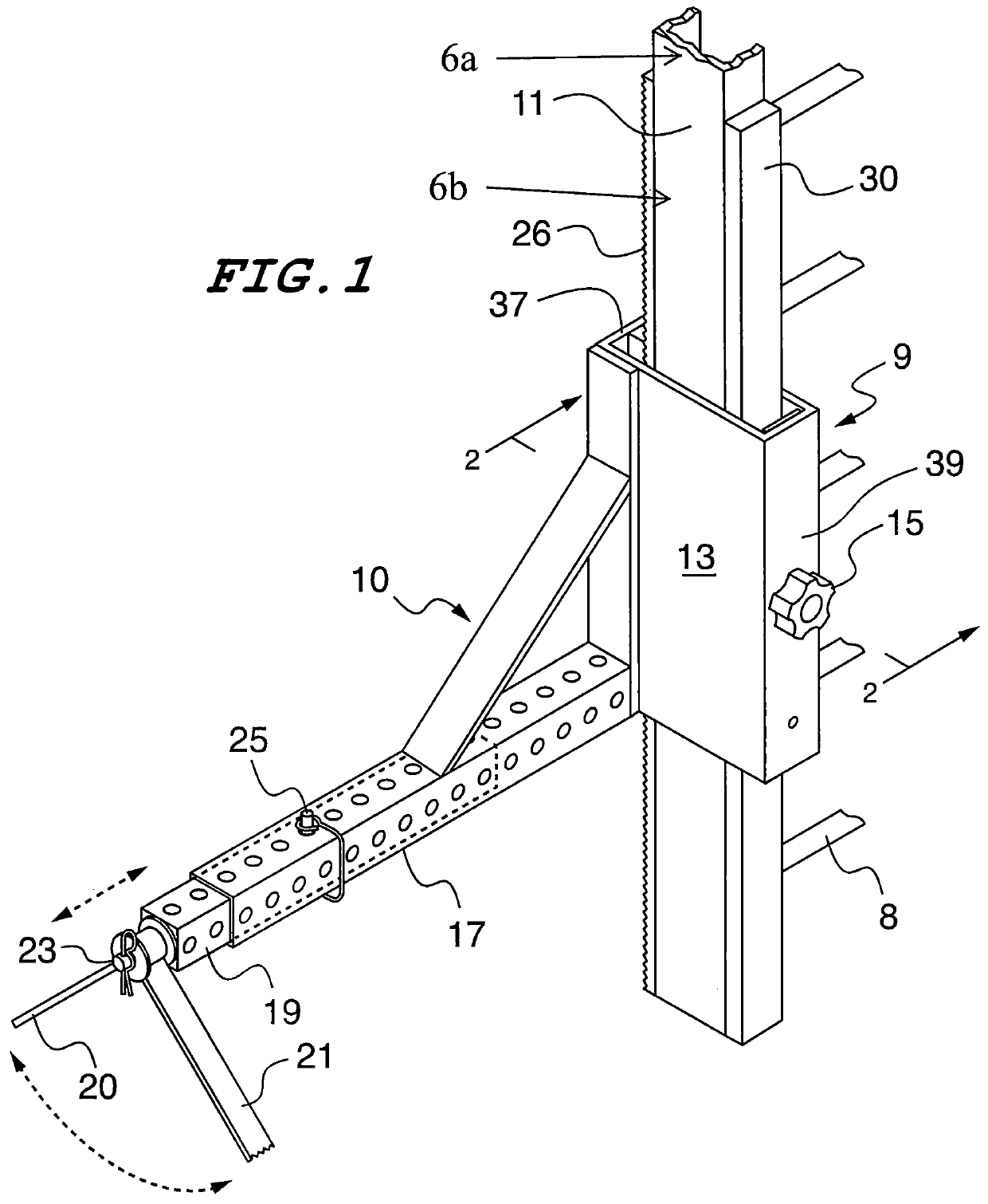
[0015]One embodiment of the ladder stabilizer of the invention comprises two main parts clamped to opposite ladder side rails adjacent a bottom portion 6b of a ladder by a unique clamping mechanism. Only the left side is shown in the drawings since a second right side is a mirror image of the left side and functions in the same way. Thus it is unnecessary for a complete understanding of the invention for both parts of the invention to be separately described, it being understood that the same structures shown here will also apply to the right side part functioning in the same way as its corresponding elements at the left. It will also be readily understood that since each side part of the pair can operate separately, the effective length of each side rail can be changed independently so that many different terrain variations can be accommodated.

[0016]Referring now to FIG. 1, this embodiment of the invention is adapted for use with a common form of a ladder that has an upper portion ...


PUM


Abstract

A ladder stabilizer comprises a pair of stabilizer brackets attached to the ladder side rails at the bottom on either side. Each bracket has a C-shaped clamping mechanism that utilizes a toothed gear rack which engages / disengages with mating teeth of a corresponding gear rack on the ladder rail. The gear-like engagement of the teeth provides a positive locking of the attachment member to the ladder. A spring and locking screw allow ease of adjustment and a positive lock at the desired location along the ladder side rail. The rack is attached longitudinally along the length of each rail to provide a range of length adjustment to the feet. This permits one side to be longer than the other to accommodate a laterally sloping terrain. The brackets have rotatable, laterally extending A-frames with ground-engaging feet which self-adjust to a terrain which is sloping from front-to-back or vice versa.

Description

RELATED APPLICATIONS[0001]This is a non-provisional patent application related to provisional application No. 62 / 547,795 filed Aug. 19, 2017 entitled, “Ladder Stabilizer and Leveler” priority from which is hereby claimed.FIELD OF THE INVENTION[0002]The present invention relates in general to a device which stabilizes a ladder to prevent it from tipping or slipping while in use. Furthermore it relates to those ladder stabilizers which also permit the base of the ladder to adjust to a sloping terrain to provide a level footing.BACKGROUND OF THE INVENTION[0003]Due to the many accidents that are result of using ladders there have been many attempts to provide a ladder with at stabilizing feature at the base of the ladder. Professional painters, carpenters and utility workers who use ladders in their work daily are most often the victims of ladder accidents. Too, the average home owner has ladder falls due to their inexperience with proper ladder use.[0004]Among the previous attempts to ...

Claims


Application Information

Patent Timeline
Patent Type & Authority Patents(United States)
IPC IPC(8): E06C7/42E06C1/06E06C7/44
CPCE06C7/423E06C1/06E06C7/44
Inventor KAZANJIAN, DAVID
Owner KAZANJIAN DAVID
Why Eureka
Try Eureka