Patient interface with an integral cushion and nasal pillows

a patient interface and cushion technology, applied in the field of patient interfaces, can solve the problems of compromising the seal between the patient and the nasal pillows, the patient's discomfort, and the large and bulky headgear assembly

Active Publication Date: 2007-04-26
PHILIPS RS NORTH AMERICA LLC
View PDF11 Cites 168 Cited by
  • Summary
  • Abstract
  • Description
  • Claims
  • Application Information

AI Technical Summary

Benefits of technology

[0013] These and other objects, features, and characteristics of the present invention, as well as the methods of operation and functions of the related elements of structure and the combination of parts and economies of manufacture, will become more apparent upon consideration of the following description and the appended claims with reference to the accompanying drawings, all of which form a part of this specification, wherein like reference numerals designate corresponding parts in the various figures. It is to be expressly understood, however, that the drawings are for the purpose of illustration and description only and are not intended as a definition of the limits of the invention. As used in the specification and in the claims, the singular form of “a”, “an”, and “the” include plural referents unless the context clearly dictates otherwise.

Problems solved by technology

One problem that can arise is that in order for the mask to maintain a seal without any undue gas leaks around the periphery of the mask, the mask is often compressed against the patient's face with too much force, causing discomfort.
In addition, it is often necessary to utilize a rather large and bulky headgear assembly to properly support and locate the patient interface.
This configuration tends to pry the patient's nose upward which may result in discomfort for some patients.
Secondly, one of the strengths of this device is that it minimized the degree of contact with the patient's face; yet, this also presents a drawback since the prying force is concentrated in a small region.
Furthermore, properly orienting the device in order to affect an adequate seal may require making multiple adjustments to the headgear assembly.
In addition, nasal pillows may lack the stability needed which could ultimately result in compromising the seal between the patient and the nasal pillows.

Method used


Image

  • Patient interface with an integral cushion and nasal pillows
  • Patient interface with an integral cushion and nasal pillows
  • Patient interface with an integral cushion and nasal pillows

Examples


Embodiment Construction

[0026] The present invention will be described with reference to the accompanying figures where like reference numbers correspond to like elements.

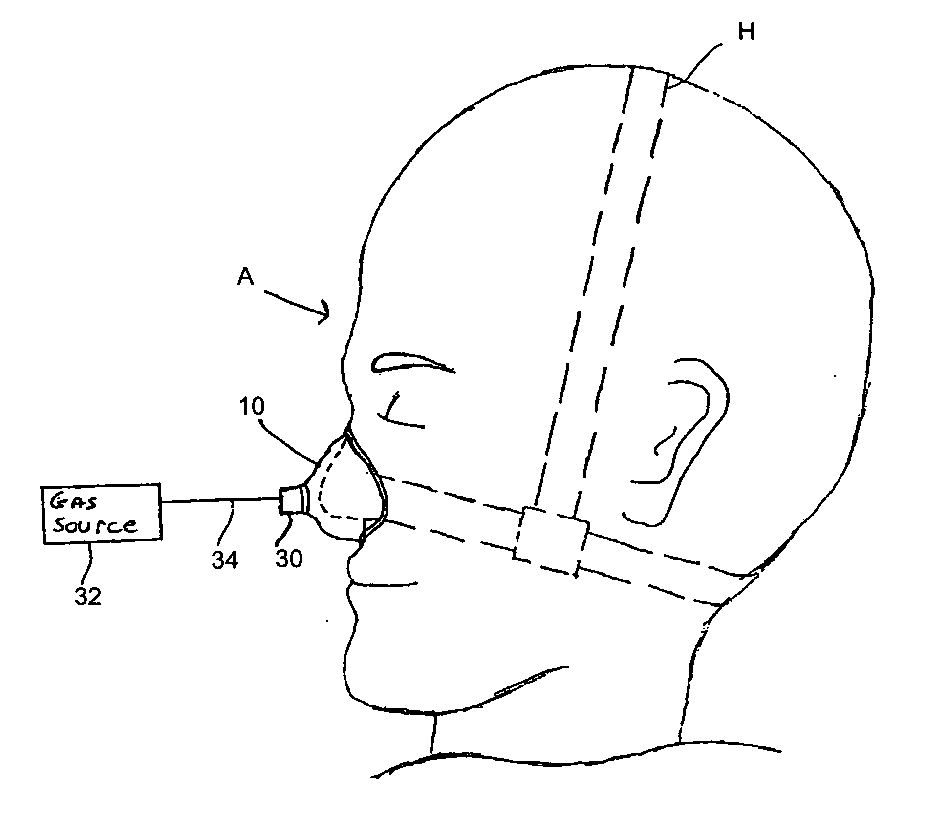
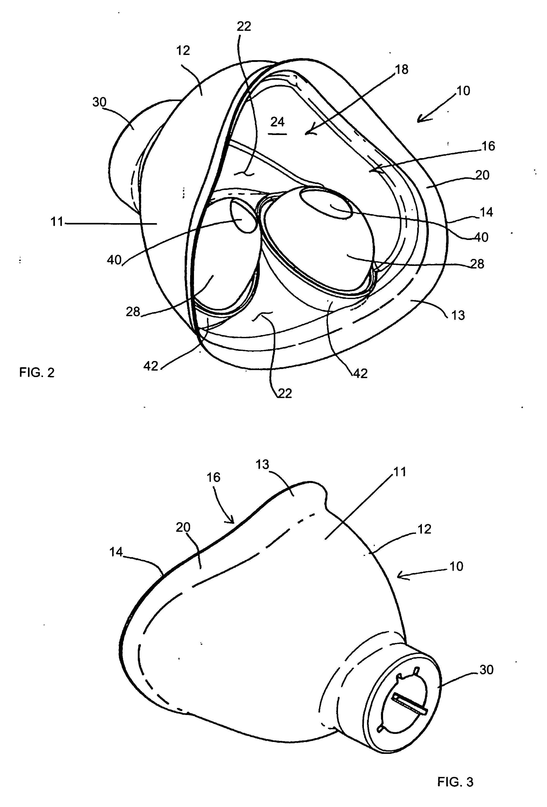
[0027] With reference to FIGS. 2-4, the present invention relates to a patient interface 10 comprising a member 11 having a shell portion 12 and a cushion portion 13 with a peripheral edge 14 surrounding an opening 16 into an interior 18 of patient interface 10. The cushion 13 includes a flange 20 that, in the illustrated embodiment, flares outwardly away from interior 18 to provide additional clearance within the interior 18.

[0028] With reference to FIG. 5 and with continuing to reference to FIGS. 2-4, patient interface 10 includes a partition 22 that separates interior 18 into a first chamber 24, configured to receive the nose of a patient, and a second chamber 26. Patient interface 10 further includes a pair of nasal pillows 28 integral with partition 22 and projecting therefrom into first chamber 24 for full, or partial, insertion i...


PUM


Abstract

The patient interface (10) of the present invention includes a pair of nasal pillows (28) for delivery of gas. The nasal pillows (28) project from a partition (22) that separates an interior of the patient interface into a first chamber (24) that is configured to receive the nose of a patient when the patient interface is mounted operatively on the face of the patient and into which the nasal pillows (28) project and a second chamber (26) that has a port (30) for delivery of gas to and from the nasal pillows (28) via the second chamber (26).

Description

PRIORITY CLAIM [0001] This application claims priority under 35 U.S.C. § 119(e) from provisional U.S. patent application No. 60 / 729,516 filed Oct. 24, 2005 the contents of which are incorporated herein by reference.TECHNICAL FIELD [0002] The present invention generally relates to a patient interface for use in a pressure support system that supplies a flow of gas to the airway of a patient, and, in particular, to a patient interface that includes a support having an integral nasal cushion and integral nasal pillows. BACKGROUND OF THE INVENTION [0003] There are numerous situations where it is necessary or desirable to deliver a flow of breathing gas non-invasively to the airway of a patient, i.e., without intubating the patient or surgically inserting a tracheal tube in their esophagus. For example, it is known to ventilate a patient using a technique known as non-invasive ventilation. It is also known to deliver continuous positive airway pressure (CPAP) or variable airway pressure,...

Claims


Application Information

Patent Timeline
Patent Type & Authority Applications(United States)
IPC IPC(8): A62B18/02A61M15/08
CPCA61M16/0666A61M16/0683A61M2210/0618A61M16/0616A61M16/0611
Inventor HO, PETER CHI FAIJIANG, JIAN-ANZHU, HAI-YAN
Owner PHILIPS RS NORTH AMERICA LLC
Why Eureka
Try Eureka