Connector

a technology of connecting parts and connectors, applied in the direction of coupling device connection, securing/insulating coupling contact members, electrical devices, etc., can solve the problem that the terminal fitting cannot rotate into a position, and achieve the effect of easy engagement of the erroneous insertion prevention part and easy formation

Active Publication Date: 2012-06-14
SUMITOMO WIRING SYST LTD
View PDF8 Cites 4 Cited by
  • Summary
  • Abstract
  • Description
  • Claims
  • Application Information

AI Technical Summary

Benefits of technology

[0007]The invention relates to a connector comprising a housing with a cavity and a terminal fitting accommodated in the cavity. The terminal fitting has an outwardly projecting locking strip and an inner surface of the cavity has an erroneous insertion prevention part that engages the locking strip when the terminal fitting is inserted into the cavity in an erroneous posture or orientation about an axis thereof, thereby preventing erroneous insertion of the terminal fitting into the cavity.
[0008]At least one of a peripheral surface of the terminal fitting and the inner surface of the cavity may be round. A lance preferably projects from the inner surface of the cavity and the terminal fitting preferably has an engagement part that engages the lance when a force in a removal direction is generated. The inner surface of the cavity preferably has a rotation prevention part to be locked to the locking strip when the terminal fitting is accommodated in the cavity, thus preventing the terminal fitting from rotating more than a predetermined amount about the axis. As a result, the terminal fitting cannot rotate into a position where the engagement part no longer engages the lance. Therefore positive locking of the terminal fitting in the cavity is assured.
[0010]The erroneous insertion prevention part and the rotation prevention part preferably are formed integrally on an inner surface of the housing. Thus, the erroneous insertion prevention part and the rotation prevention part can be formed easily.
[0011]The locking strip preferably has left and right parts. Thus, the locking strip can be locked easily to the erroneous insertion prevention part, and the erroneous insertion prevention part can be formed in a small angular region.
[0012]Two locking strips preferably are symmetrical in a left-to-right direction and incline up or down with respect to a horizontal direction. Thus, the locking strip easily engages the erroneous insertion prevention part when the terminal fitting is inserted into the cavity in an inverted posture.
[0013]The terminal fitting preferably has a terminal connection part to be connected to a mating male terminal fitting, a wire connection part to be connected to an electric wire, and a plate-shaped coupling continuous with the terminal connection part and the wire connection part. The locking strip preferably is integral with a side edge of the coupling. Thus, the locking strip can be formed easily while producing the terminal fitting.

Problems solved by technology

As a result, the terminal fitting cannot rotate into a position where the engagement part no longer engages the lance.

Method used


Image

  • Connector
  • Connector
  • Connector

Examples


Embodiment Construction

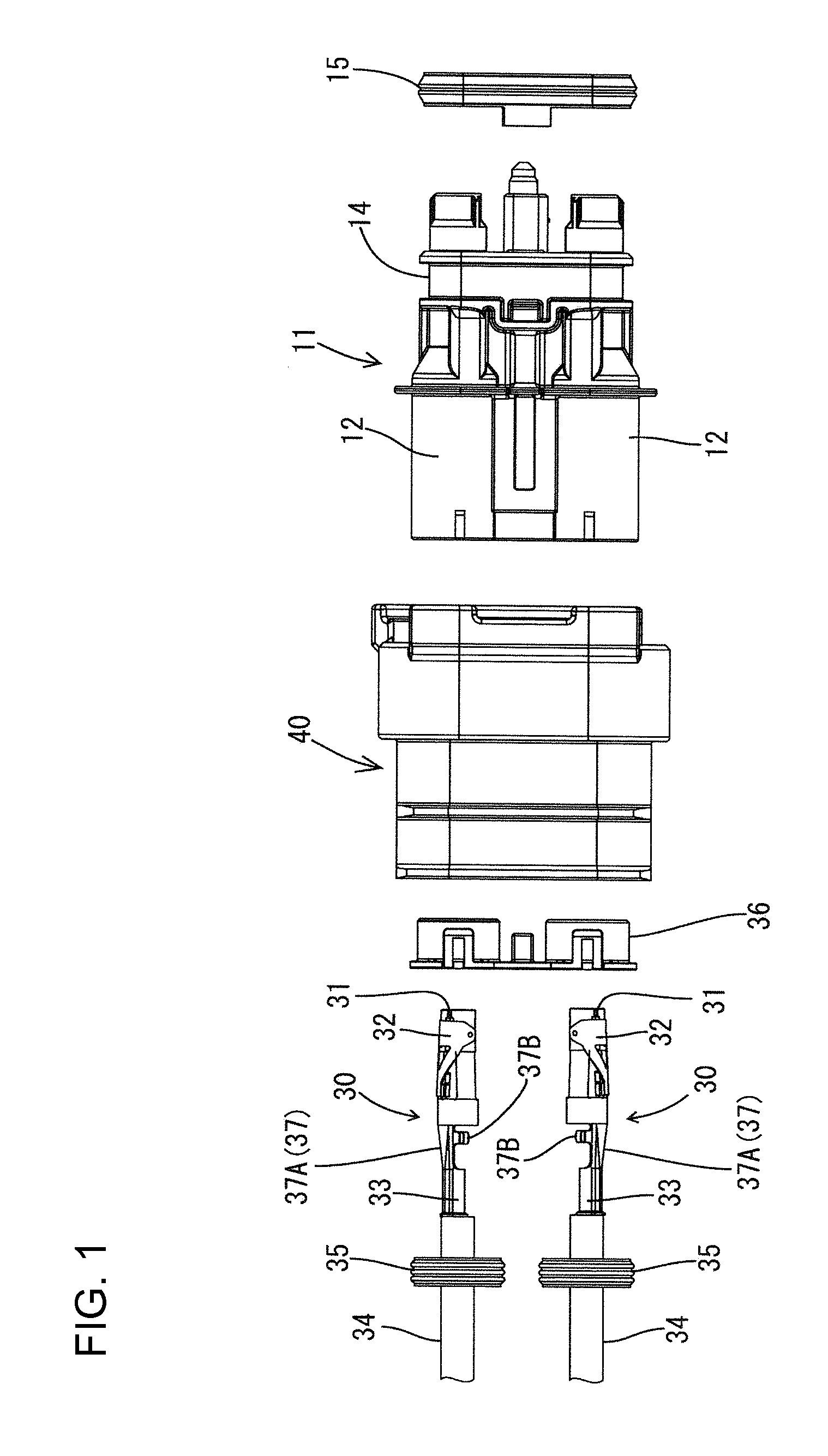
[0025]A connector in accordance with the invention is identified by the numeral 10 in FIG. 8. The connector 10 is mounted on a car, such as a hybrid car or an electric car, and is disposed on a path for supplying an electric power between a battery and equipment, such as an inverter. The connector 10 is a female connector that can be fit on a mating male connector (not shown) fixed to a case of the equipment. In the following description, the left side in FIG. 1 is the front, whereas the right side is the rear. The vertical direction and the left-to-right direction correspond to the orientation of FIG. 7.

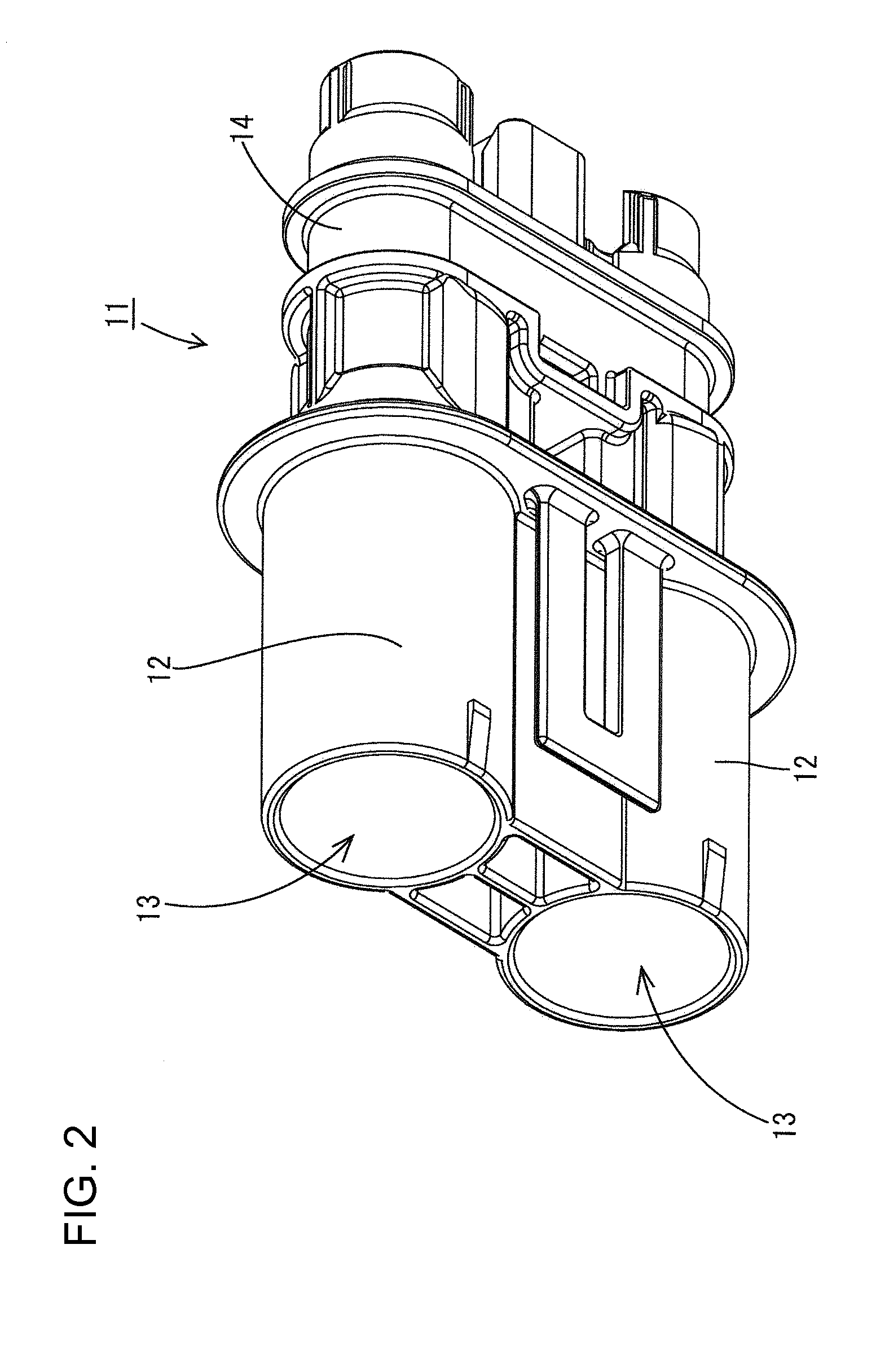
[0026]As shown in FIG. 1, the connector 10 has a housing 11 made of a synthetic resin, a terminal fitting 30 held by the housing 11, and a die-cast aluminum shielding shell 40 fit on the housing 11.

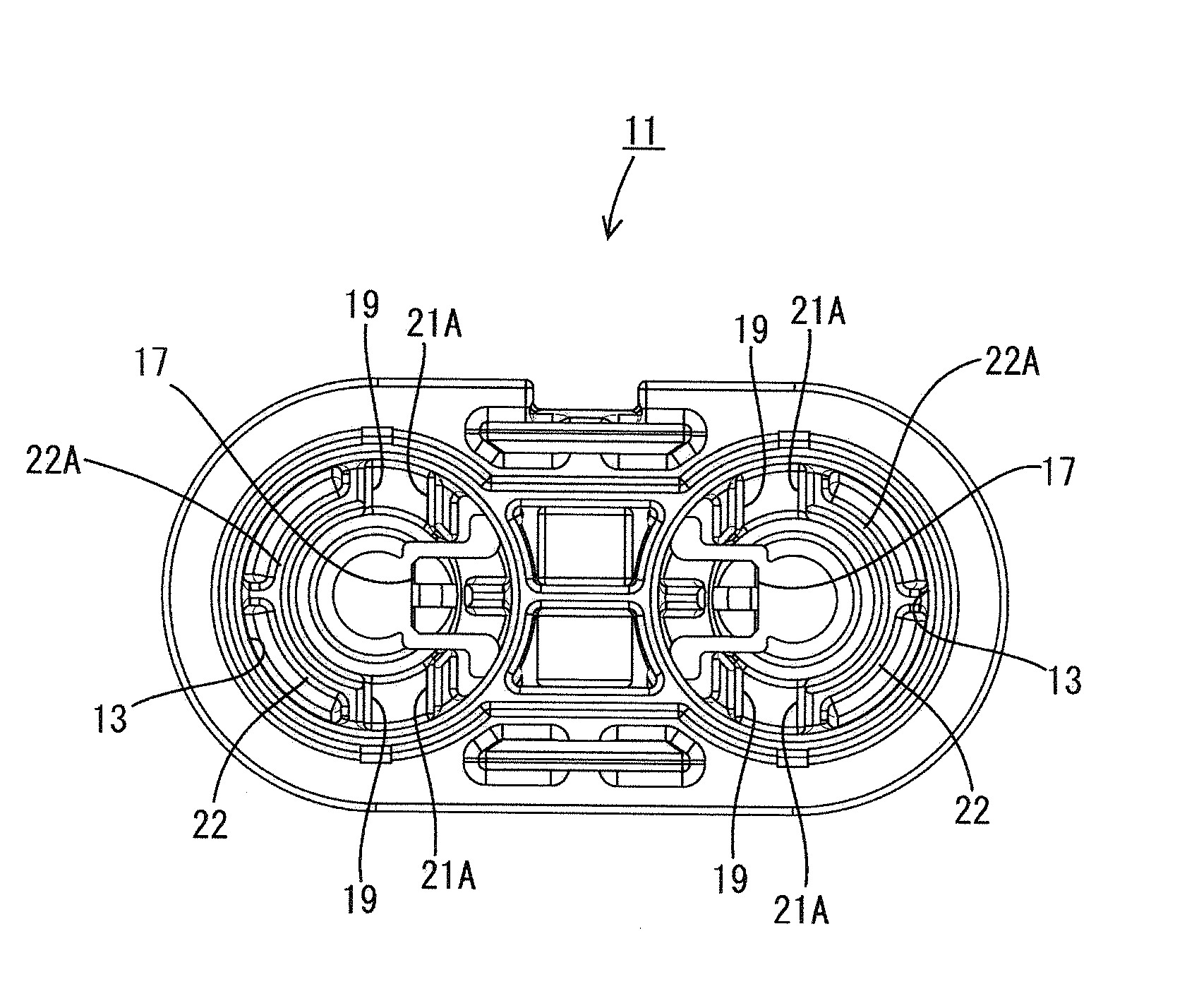
[0027]The housing 11 has two laterally spaced terminal fitting holding parts 12, 12, integral with each other and spaced at a predetermined distance. A cavity 13 is formed inside each ter...


PUM


Abstract

A connector (10) has a housing (11) with a cavity (13) and a terminal fitting (30) accommodated inside the cavity (13). A locking strip (37B) projects out on the terminal fitting (30). An inner surface of the cavity (13) has an erroneous insertion prevention part (22A) that engages the locking strip (37B) when the terminal fitting (30) is inserted into the cavity (13) in a posture erroneous in an orientation about an axis thereof, thus preventing erroneous insertion of the terminal fitting (30) into the cavity (13).

Description

BACKGROUND OF THE INVENTION[0001]1. Field of the Invention[0002]The invention relates to a connector.[0003]2. Description of the Related Art[0004]Hybrid cars and electric cars have an inverter and a battery that are connected to each other by a power electric wire that has connectors at respective ends thereof. Each connector has a terminal fitting connected with the end of the electric wire. The terminal fitting is inserted into the insertion hole or cavity of a connector housing. A lance projects radially from the periphery of the terminal fitting and is locked to the end surface of a hole formed orthogonally to the insertion hole.[0005]The terminal fitting should be inserted into the cavity in a normal posture. However, there is a fear that the terminal fitting can be accommodated inside the cavity in an erroneous posture (e.g. inverted) and hence the lance will not lock to the hole in the cavity.[0006]The invention has been completed in view of the above-described situation. Thu...

Claims


Application Information

Patent Timeline
Patent Type & Authority Applications(United States)
IPC IPC(8): H01R13/40
CPCH01R13/4223
Inventor ISHIBASHI, TAKESHI
Owner SUMITOMO WIRING SYST LTD
Why Eureka
Try Eureka