Button head tie

a button head tie and button head technology, applied in the direction of hose connections, snap fasteners, buckles, etc., can solve the problems of bending shear stress, tie strap breakage, and relatively thick tie straps that have relatively narrow side rails, and achieve the effect of low strap insertion for

Active Publication Date: 2010-12-09
HELLERMANNTYTON CORP
View PDF14 Cites 48 Cited by
  • Summary
  • Abstract
  • Description
  • Claims
  • Application Information

AI Technical Summary

Benefits of technology

[0013]Consistent low strap insertion force when the strap is inserted into button head between the aperture ramp and wedge. This is accomplished by eliminating the shelf or “step” feature and replacing it with temporary / collapsible standoff tabs that partially elevate the wedge out of the aperture—providing an opening for strap passage.

Problems solved by technology

However, button head ties of current design and manufacture have several problems associated with their use.
For example, it has been found that tie straps that are relatively thick and that have relatively narrow side rails are much more susceptible to bending shear stresses and tie strap breakage.
It has also been found that tie straps that have serrations with relatively sharp corners, or peaks, tend to produce high stress concentrations along the tie strap, also making them much more susceptible to tie strap breakage.
Also observed in previous button head tie strap designs is the fact that tie straps can be inadvertently inserted at an angle into the button head aperture.
This is due to the internal geometry of the button head aperture side walls which forms excessive clearance for the strap width.
During inadvertent angled strap insertion, proper engagement of the strap serrations with the wedge teeth is not possible which results in unexpected release of the bundle.
Button head ties of previous designs and manufacture also limit the overall tensile strength of the loop formed by the tie strap.
Subsequently, this inventor has realized that the entire surrounding geometry, for both the button head and wedge, required to create the “shelf,”“stop” or “step” configurations mentioned above enables the “unexpected release of the bundle” and, furthermore, limits the ultimate potential wedging action of the button head tie.
Also observed in previous designs is the difficulty of inserting the strap into the button head when the button head aperture is concealing the wedge because the button head is free to slide in the region of the wedge, thereby sometimes blocking the open passageway the strap is intended to pass through.

Method used


Image

  • Button head tie
  • Button head tie
  • Button head tie

Examples


Embodiment Construction

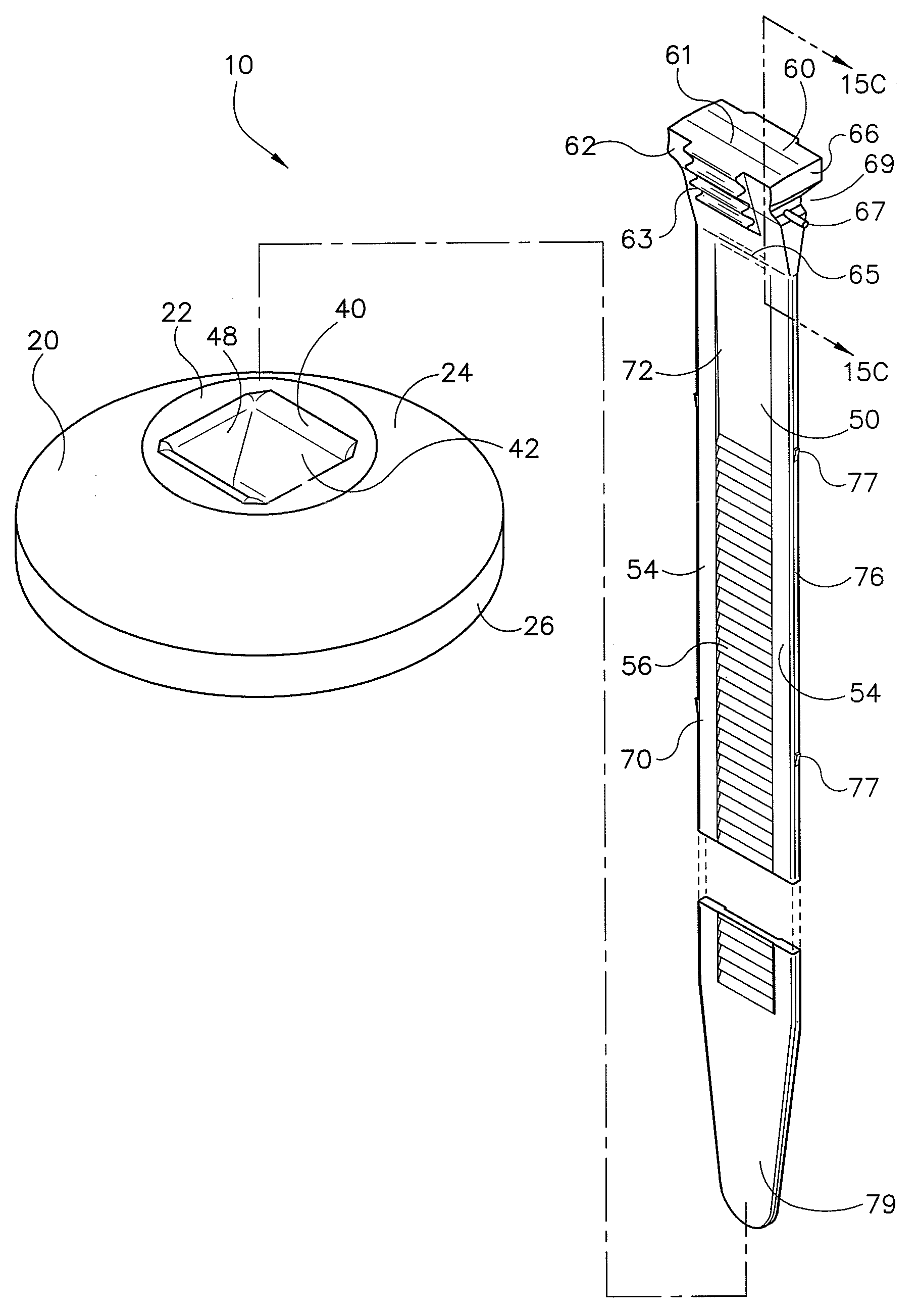
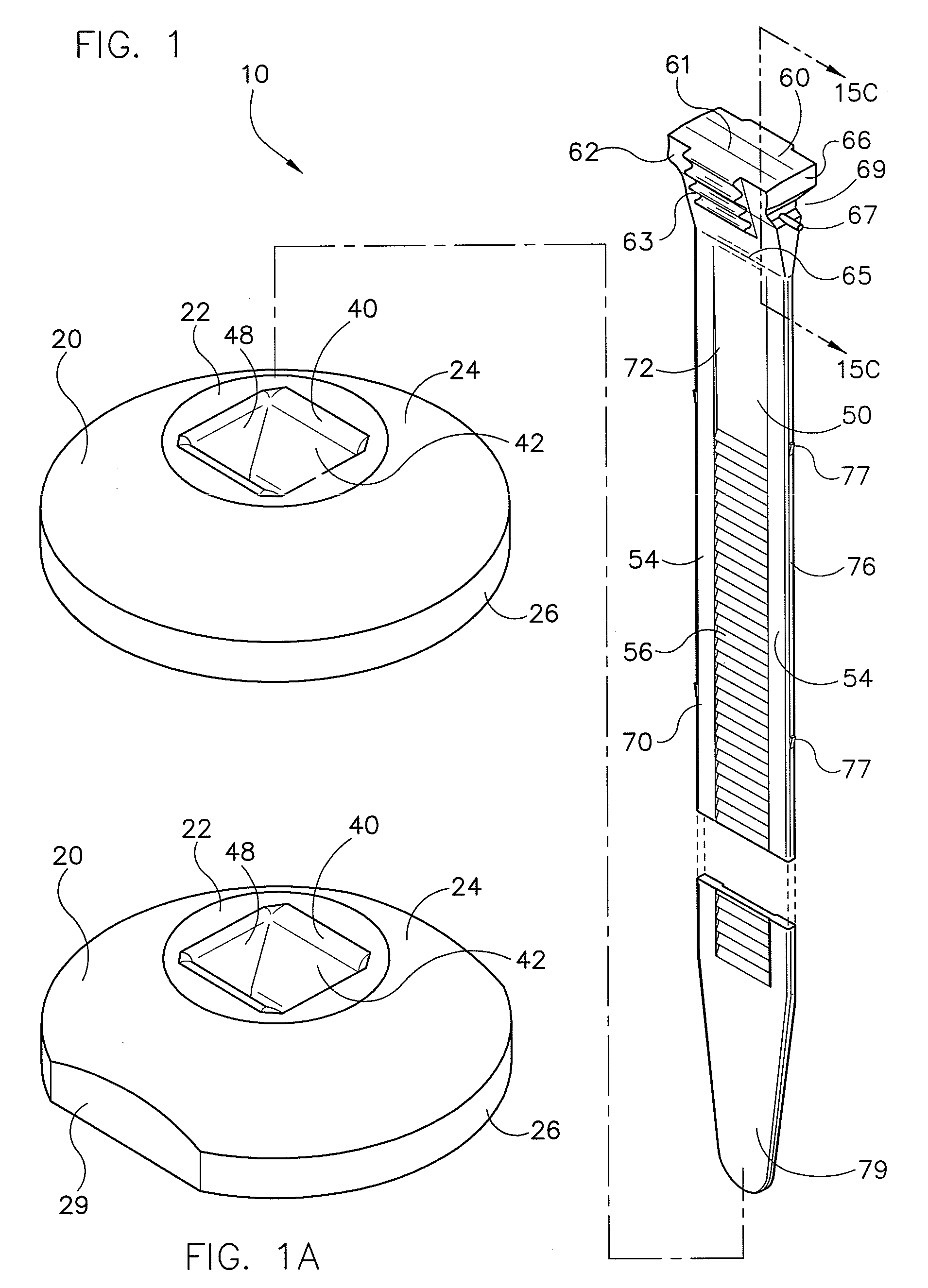
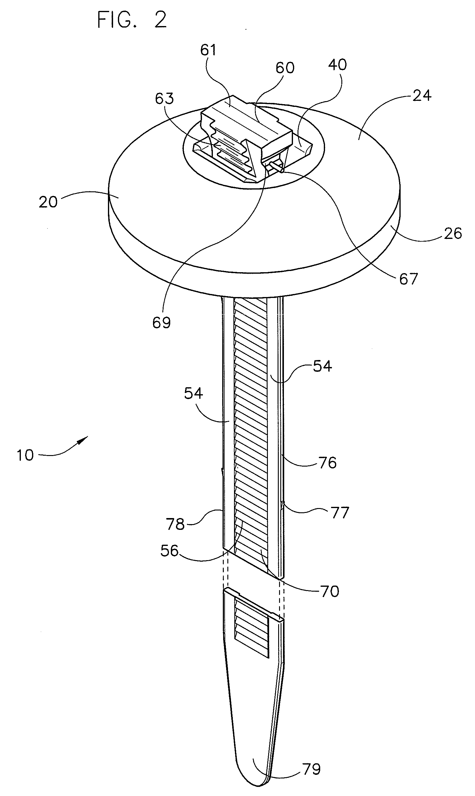
[0049]Referring now to the drawings in detail, FIG. 1 illustrates the preferred embodiment of the new and improved button head tie 10 constructed in accordance with the present invention. The new and improved button head tie 10 includes two principal components: a button head, generally identified 20, and a tie strap, generally identified 50.

[0050]As shown in FIG. 1, the button head 20 includes a top surface 22, a spherical sloped portion 24 that extends downwardly from the top surface 22, and a circumferential rim 26. The top surface 22 of the button head 20 includes a centrally-disposed aperture 40, the aperture 40 extending fully through an otherwise solid, and axially-disposed, central hub 30 of the button head 20. See FIGS. 4-8 and 10. The button head 20 of the preferred embodiment also includes a substantially planar bottom base 28. The central hub 30 of the button head 20 extends from the top surface 22 to the planar bottom base 28. Extending further downwardly from the plana...


PUM


Abstract

A button head tie has a button head and a tie strap. The button head is a generally flat member having an aperture for receiving the tie strap. The aperture includes lead-in ramps to facilitate tie strap insertion and is configured to prevent angled tie strap insertion. The tie strap is a flat elongate member having a wedge that is captured within the aperture. The remainder of the strap passes through the aperture. The wedge and strap have teeth and serrations on both sides, respectively, the teeth and serrations being engageable. In use, the strap is looped around a bundle and inserted into the aperture to either side of the wedge. Strap insertion force is reduced by standoff tabs which elevate the wedge out of aperture, temporarily, during installation. When loop tension is applied to the bundle, the wedge is pulled into the aperture, compressively locking the strap.

Description

FIELD OF THE INVENTION[0001]This invention relates generally to devices used to bundle and secure elongated items such as wires, cables, hoses, and the like, together and also to attach the bundle to a mounting surface. More particularly, it relates to a new and improved button head tie which includes a uniquely configured wedge at one end of the elongate tie strap component. The improved button head component is uniquely configured with a new aperture for receiving the tie strap wedge and a portion of the tie strap within it for securing a bundle of elongated items to a mounting surface. Further the button head is greatly reinforced with a radial truss work structure.BACKGROUND OF THE INVENTION[0002]Molded plastic cable ties are known in the art and are used to secure a variety of elongated items such as wires, cables, hoses, tubes, in tight bundles. Specialized button head ties are also known in the art. A button head tie is essentially a plastic tie strap product constructed from...

Claims


Application Information

Patent Timeline
Patent Type & Authority Applications(United States)
IPC IPC(8): B65D63/10B65D63/00
CPCB65D63/14F16L3/2334Y10T24/141Y10T24/1498Y10T24/44026Y10T24/1406Y10T24/14
Inventor GEIGER, GERARD G.
Owner HELLERMANNTYTON CORP
Why Eureka
Try Eureka